Callout | Feature |
| Function |
|
|
|
|
J. | USB 2.0 Port |
| Allows you to attach a USB component to the front of the chassis. |
|
|
|
|
K. | NMI Button |
| Puts the server in a |
|
|
|
|
L. | Video Port |
| Allows you to attach a video monitor to the front of the chassis. |
|
|
| The front and rear video ports cannot be used at the same time. |
|
|
|
|
|
| Figure 10. Standard Control Panel | |
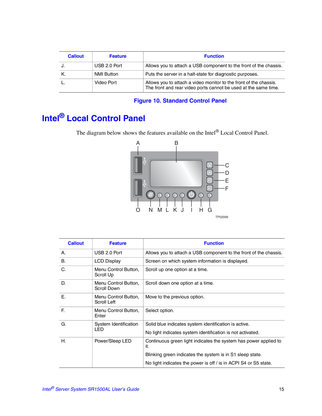
Intel® Local Control Panel
The diagram below shows the features available on the Intel® Local Control Panel.
| A | B |
|
| C |
|
| D |
|
| E |
|
| F |
| O | N M L K J I H G |
|
| TP02099 |
Callout | Feature | Function |
A. | USB 2.0 Port | Allows you to attach a USB component to the front of the chassis. |
B. | LCD Display | Screen on which system information is displayed. |
C. | Menu Control Button, | Scroll up one option at a time. |
| Scroll Up |
|
D. | Menu Control Button, | Scroll down one option at a time. |
| Scroll Down |
|
E. | Menu Control Button, | Move to the previous option. |
| Scroll Left |
|
F. | Menu Control Button, | Select option. |
| Enter |
|
G. | System Identification | Solid blue indicates system identification is active. |
| LED | No light indicates system identification is not activated. |
|
| |
H. | Power/Sleep LED | Continuous green light indicates the system has power applied to |
|
| it. |
|
| Blinking green indicates the system is in S1 sleep state. |
|
| No light indicates the power is off / is in ACPI S4 or S5 state. |
Intel® Server System SR1500AL User’s Guide | 15 |