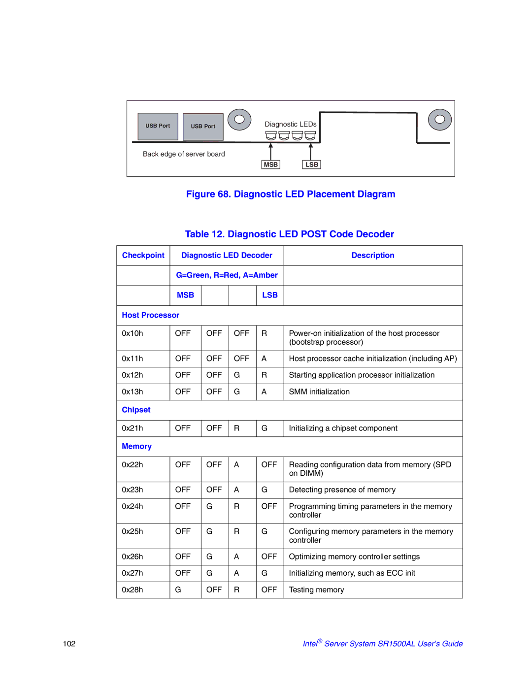
USB Port | USB Port | Diagnostic LEDs | |
Back edge of server board |
|
| |
|
| MSB | LSB |
Figure 68. Diagnostic LED Placement Diagram
Table 12. Diagnostic LED POST Code Decoder
Checkpoint | Diagnostic LED Decoder | Description | |||
|
|
| |||
| G=Green, R=Red, A=Amber |
| |||
|
|
|
|
|
|
| MSB |
|
| LSB |
|
|
|
|
|
|
|
Host Processor |
|
|
|
| |
|
|
|
|
|
|
0x10h | OFF | OFF | OFF | R | |
|
|
|
|
| (bootstrap processor) |
|
|
|
|
|
|
0x11h | OFF | OFF | OFF | A | Host processor cache initialization (including AP) |
|
|
|
|
|
|
0x12h | OFF | OFF | G | R | Starting application processor initialization |
|
|
|
|
|
|
0x13h | OFF | OFF | G | A | SMM initialization |
|
|
|
|
|
|
Chipset |
|
|
|
|
|
|
|
|
|
|
|
0x21h | OFF | OFF | R | G | Initializing a chipset component |
|
|
|
|
|
|
Memory |
|
|
|
|
|
|
|
|
|
|
|
0x22h | OFF | OFF | A | OFF | Reading configuration data from memory (SPD |
|
|
|
|
| on DIMM) |
|
|
|
|
|
|
0x23h | OFF | OFF | A | G | Detecting presence of memory |
|
|
|
|
|
|
0x24h | OFF | G | R | OFF | Programming timing parameters in the memory |
|
|
|
|
| controller |
|
|
|
|
|
|
0x25h | OFF | G | R | G | Configuring memory parameters in the memory |
|
|
|
|
| controller |
|
|
|
|
|
|
0x26h | OFF | G | A | OFF | Optimizing memory controller settings |
|
|
|
|
|
|
0x27h | OFF | G | A | G | Initializing memory, such as ECC init |
|
|
|
|
|
|
0x28h | G | OFF | R | OFF | Testing memory |
|
|
|
|
|
|
102 | Intel® Server System SR1500AL User’s Guide |