SECTION
Before 2/15/07
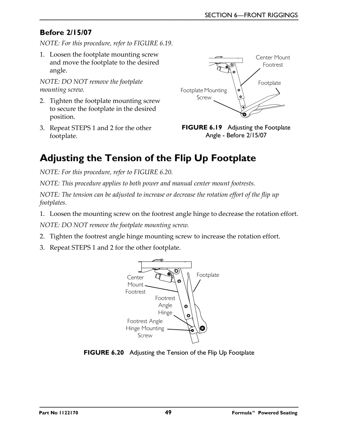
NOTE: For this procedure, refer to FIGURE 6.19.
1.Loosen the footplate mounting screw and move the footplate to the desired angle.
NOTE: DO NOT remove the footplate mounting screw.
2.Tighten the footplate mounting screw to secure the footplate in the desired position.
3.Repeat STEPS 1 and 2 for the other footplate.
Center Mount
Footrest
Footplate
Footplate Mounting
Screw
FIGURE 6.19 Adjusting the Footplate
Angle - Before 2/15/07
Adjusting the Tension of the Flip Up Footplate
NOTE: For this procedure, refer to FIGURE 6.20.
NOTE: This procedure applies to both power and manual center mount footrests.
NOTE: The tension can be adjusted to increase or decrease the rotation effort of the flip up footplates.
1. Loosen the mounting screw on the footrest angle hinge to decrease the rotation effort. NOTE: DO NOT remove the footplate mounting screw.
2.Tighten the footrest angle hinge mounting screw to increase the rotation effort.
3.Repeat STEPS 1 and 2 for the other footplate.
Center | Footplate |
| |
Mount |
|
Footrest |
|
Footrest
Angle
Hinge
Footrest Angle
Hinge Mounting
Screw
FIGURE 6.20 Adjusting the Tension of the Flip Up Footplate
Part No 1122170 | 49 | Formula™ Powered Seating |
