SECTION 5—WHEELCHAIR OPERATION
Refer to LCD Display table on page 30 for descriptions of information shown.
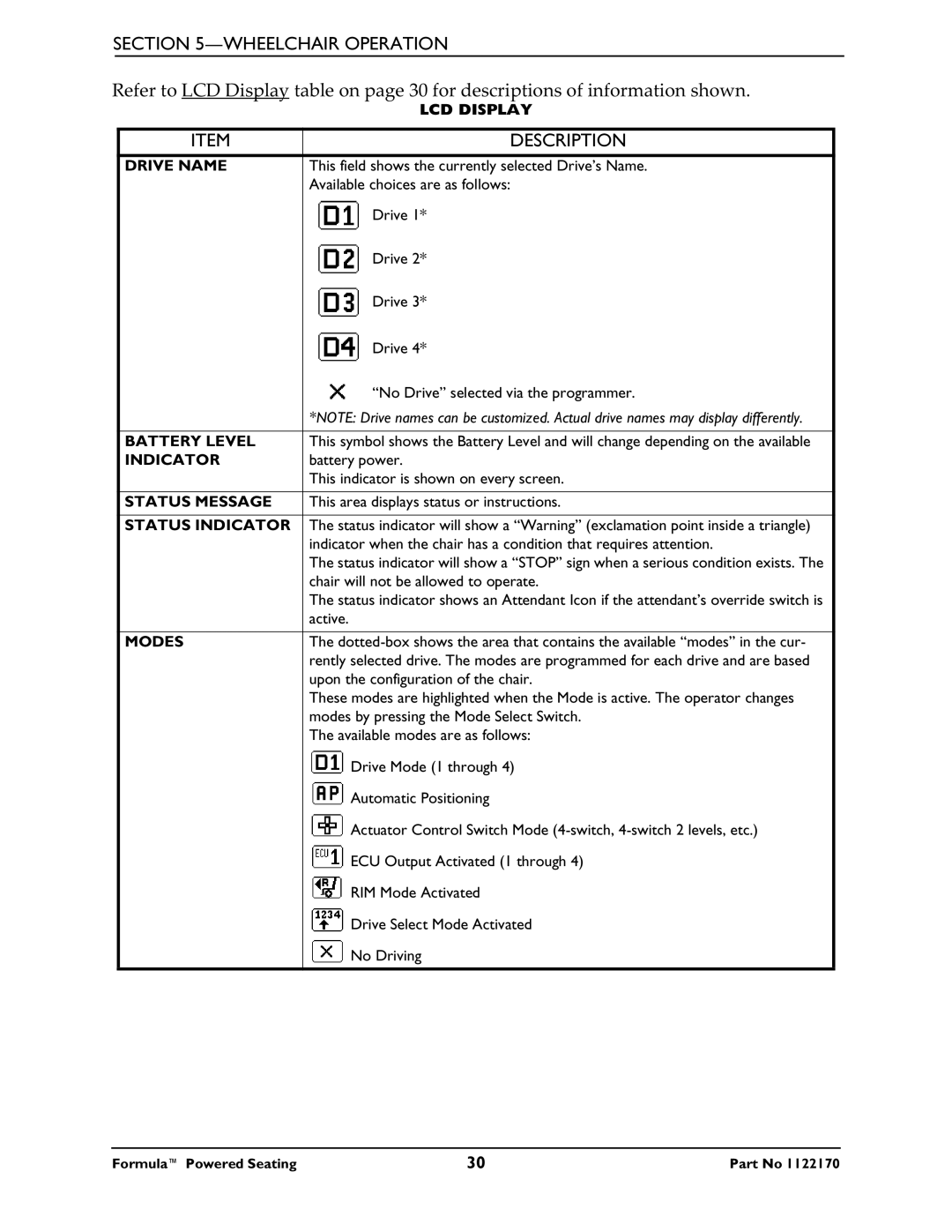
| LCD DISPLAY |
|
|
ITEM | DESCRIPTION |
|
|
DRIVE NAME | This field shows the currently selected Drive’s Name. |
| Available choices are as follows: |
| Drive 1* |
| Drive 2* |
| Drive 3* |
| Drive 4* |
| “No Drive” selected via the programmer. |
| *NOTE: Drive names can be customized. Actual drive names may display differently. |
|
|
BATTERY LEVEL | This symbol shows the Battery Level and will change depending on the available |
INDICATOR | battery power. |
| This indicator is shown on every screen. |
|
|
STATUS MESSAGE | This area displays status or instructions. |
|
|
STATUS INDICATOR | The status indicator will show a “Warning” (exclamation point inside a triangle) |
| indicator when the chair has a condition that requires attention. |
| The status indicator will show a “STOP” sign when a serious condition exists. The |
| chair will not be allowed to operate. |
| The status indicator shows an Attendant Icon if the attendant’s override switch is |
| active. |
|
|
MODES | The |
| rently selected drive. The modes are programmed for each drive and are based |
| upon the configuration of the chair. |
| These modes are highlighted when the Mode is active. The operator changes |
| modes by pressing the Mode Select Switch. |
| The available modes are as follows: |
| Drive Mode (1 through 4) |
| Automatic Positioning |
| Actuator Control Switch Mode |
| ECU Output Activated (1 through 4) |
| RIM Mode Activated |
| Drive Select Mode Activated |
| No Driving |
|
|
Formula™ Powered Seating | 30 | Part No 1122170 |