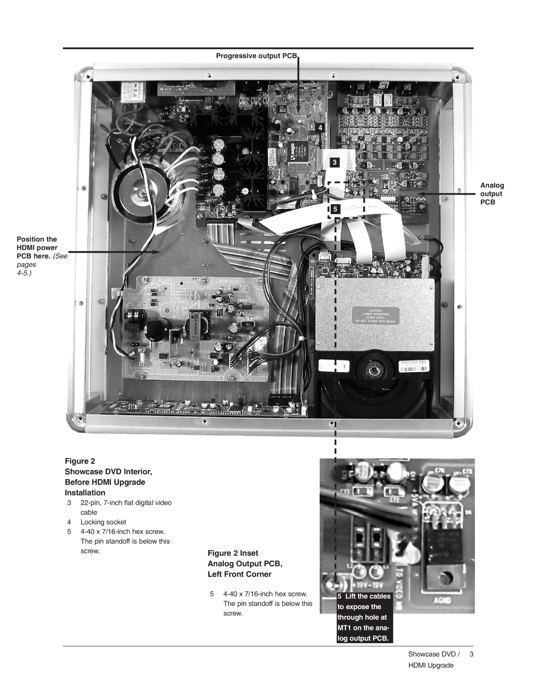
Progressive output PCB
4
3
Analog
output
PCB
5
Position the HDMI power PCB here. (See pages
Figure 2
Showcase DVD Interior,
Before HDMI Upgrade
Installation
3
4Locking socket
5
Figure 2 Inset
Analog Output PCB,
Left Front Corner
5
5Lift the cables to expose the through hole at MT1 on the ana- log output PCB.
Showcase DVD / 3
HDMI Upgrade