HDMI Upgrade
Procedure, continued
Note
Remove the plastic tags from the supplied cables and wires, before continuing the installa- tion. Add the Ty-Wrap plastic tags to cables, if needed, to keep them neatly positioned inside the chassis.
IMPORTANT
To unplug a transformer wire, pull the female fast-on connector at the end of the wire. If you pull the wire itself, instead of the connector, the wire may detach from the connector.
Steps Q–Y. Connect the Cables
Q. Release the 22-pin, 10-inch flat cable (22) from J1603 (23) on the drive PCB (This cable is affixed to the main power supply PCB. Not illustrated).
R. Connect the 22-pin, 10-inch flat cable (22) to connector J29 (24) on the HDMI adapter PCB. Orient the contacts to face the front of the Showcase DVD.
S. Connect the supplied 22-pin, 2-inch flat cable (11), with the contacts facing up, from J1002 (4) on the progressive output PCB to connector J4 (12) on the HDMI adapter PCB. Reset the tabs to lock the socket on J1002 (see Figure 5).
T.Connect the supplied 6-pin JST cable (13) from connector J7 (14) on the HDMI adapter PCB to connector J3 (15) on the HDMI power PCB (see Figure 5).
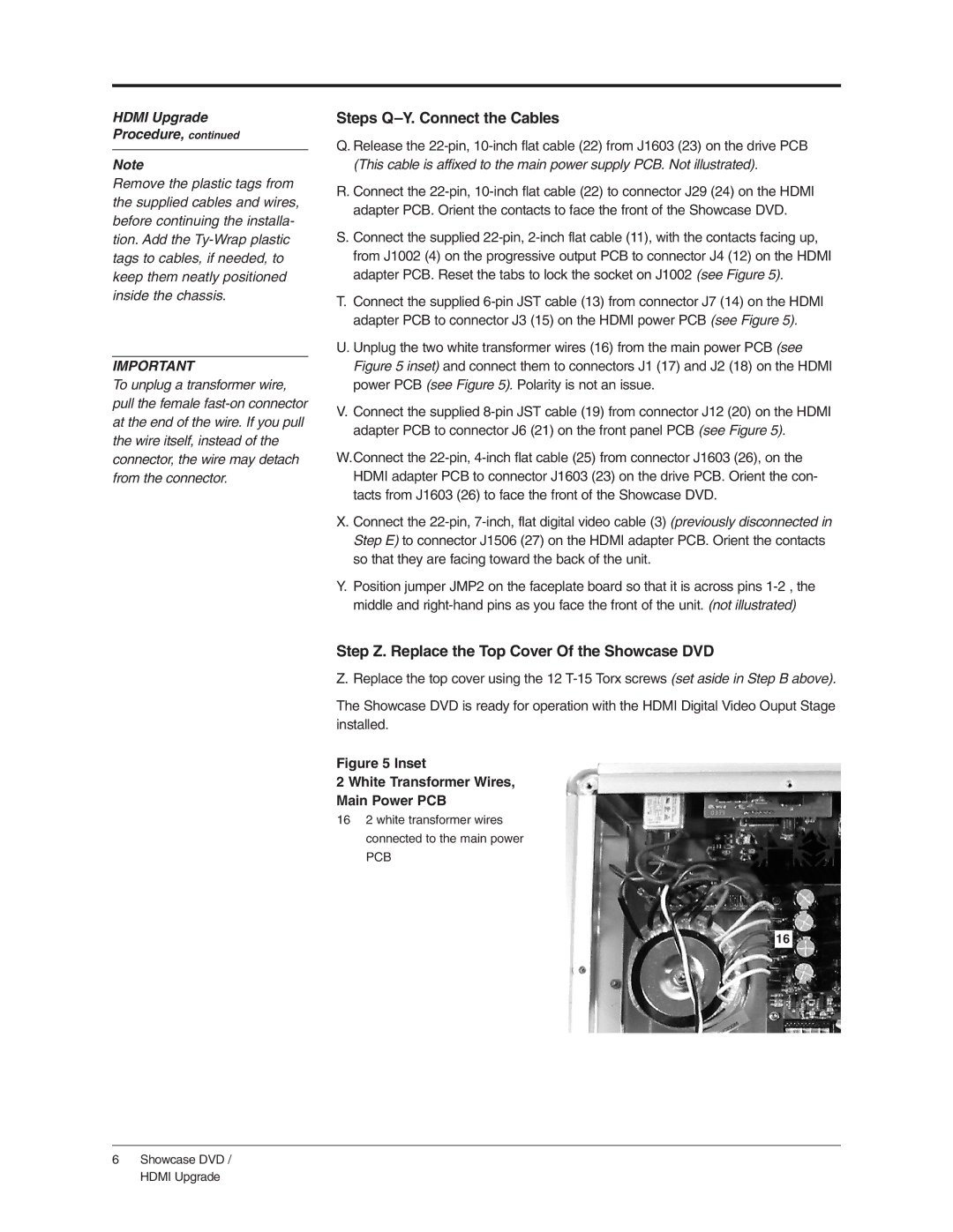
U.Unplug the two white transformer wires (16) from the main power PCB (see Figure 5 inset) and connect them to connectors J1 (17) and J2 (18) on the HDMI power PCB (see Figure 5). Polarity is not an issue.
V.Connect the supplied 8-pin JST cable (19) from connector J12 (20) on the HDMI adapter PCB to connector J6 (21) on the front panel PCB (see Figure 5).
W.Connect the 22-pin, 4-inch flat cable (25) from connector J1603 (26), on the HDMI adapter PCB to connector J1603 (23) on the drive PCB. Orient the con- tacts from J1603 (26) to face the front of the Showcase DVD.
X. Connect the 22-pin, 7-inch, flat digital video cable (3) (previously disconnected in Step E) to connector J1506 (27) on the HDMI adapter PCB. Orient the contacts so that they are facing toward the back of the unit.
Y.Position jumper JMP2 on the faceplate board so that it is across pins 1-2 , the middle and right-hand pins as you face the front of the unit. (not illustrated)
Step Z. Replace the Top Cover Of the Showcase DVD
Z. Replace the top cover using the 12 T-15 Torx screws (set aside in Step B above).
The Showcase DVD is ready for operation with the HDMI Digital Video Ouput Stage installed.
Figure 5 Inset
2 White Transformer Wires,
Main Power PCB
162 white transformer wires connected to the main power
PCB
16