Pinouts
Figure C-5. Wire Splicer
To splice the wires, cut off the end of the wire that does not extend through the connector and insert both wires into the connector. Make sure that the wire that does not extend through the connector is in as far as possible to ensure a solid connection. Make sure that the wire that does extend through the connector extends far enough on the other side to be inserted in to the DB25 connector. Carefully squeeze the connector using a pair of pliers to make sure it is fully latched.
RJ45 to DB9
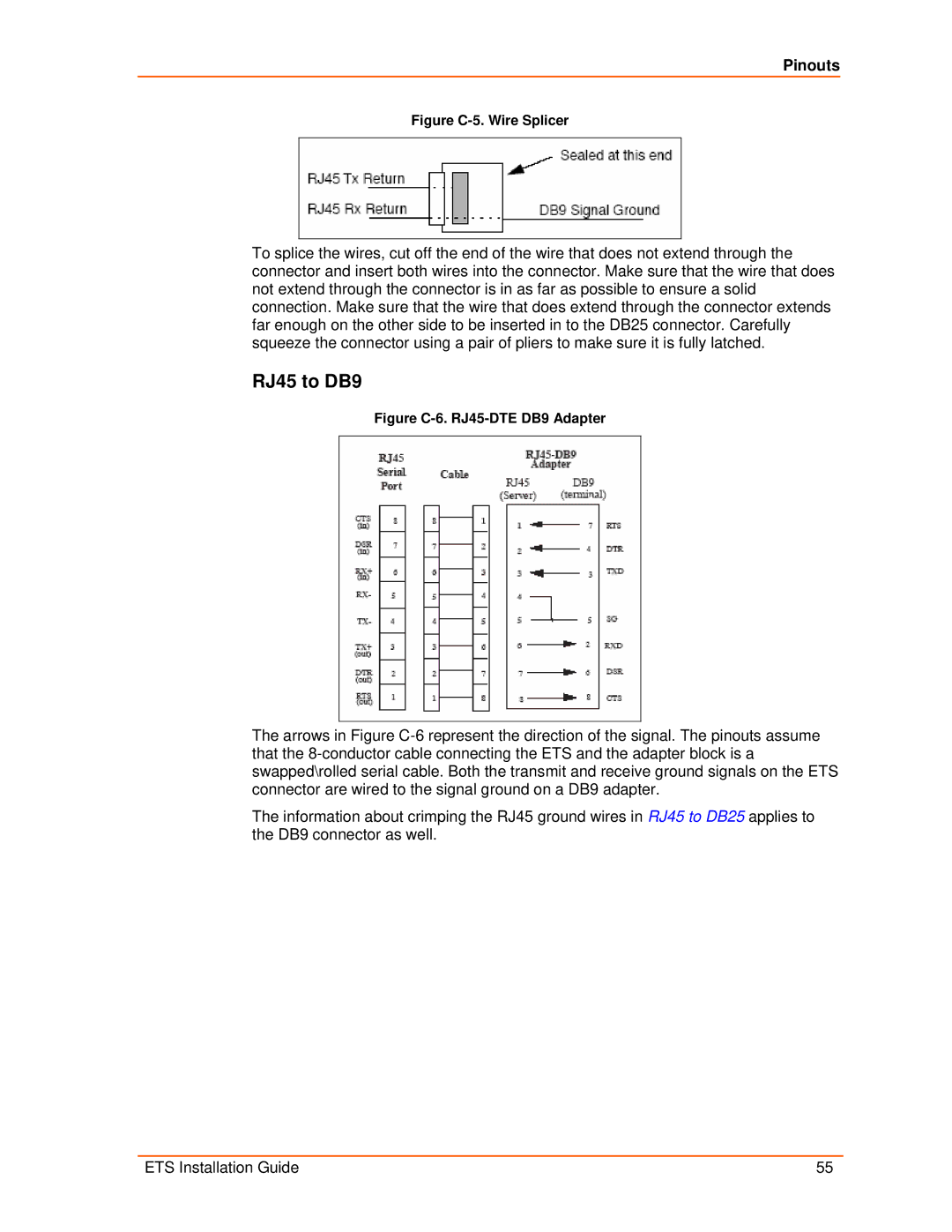
Figure C-6. RJ45-DTE DB9 Adapter
The arrows in Figure
The information about crimping the RJ45 ground wires in RJ45 to DB25 applies to the DB9 connector as well.
ETS Installation Guide | 55 |