8.Remove the memory modules. See “Installing or replacing a memory module” on page 97.
9.Remove the battery. See “Replacing the battery” on page 95.
10.Remove the rear I/O assembly to gain access to the system board. See “Replacing the rear I/O assembly” on page 84.
11.Note the locations of all cable connections on the system board and disconnect all cables. See “Locating parts on the system board” on page 69.
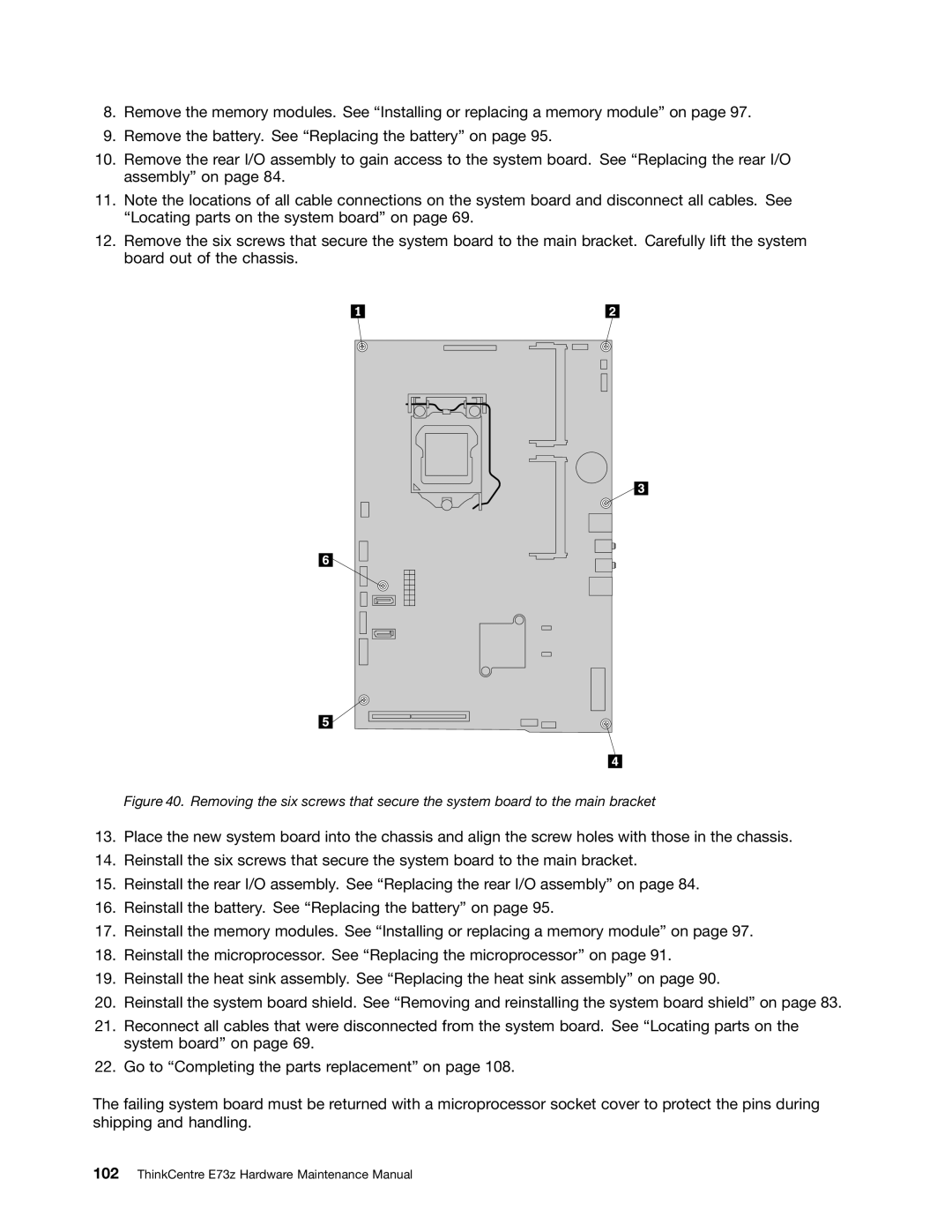
12.Remove the six screws that secure the system board to the main bracket. Carefully lift the system board out of the chassis.
Figure 40. Removing the six screws that secure the system board to the main bracket
13.Place the new system board into the chassis and align the screw holes with those in the chassis.
14.Reinstall the six screws that secure the system board to the main bracket.
15.Reinstall the rear I/O assembly. See “Replacing the rear I/O assembly” on page 84.
16.Reinstall the battery. See “Replacing the battery” on page 95.
17.Reinstall the memory modules. See “Installing or replacing a memory module” on page 97.
18.Reinstall the microprocessor. See “Replacing the microprocessor” on page 91.
19.Reinstall the heat sink assembly. See “Replacing the heat sink assembly” on page 90.
20.Reinstall the system board shield. See “Removing and reinstalling the system board shield” on page 83.
21.Reconnect all cables that were disconnected from the system board. See “Locating parts on the system board” on page 69.
22.Go to “Completing the parts replacement” on page 108.
The failing system board must be returned with a microprocessor socket cover to protect the pins during shipping and handling.