Forms Printer 248x/249x
United States Government Restricted Rights
Contents
Page
Epson Mode Printer Commands
Barcodes
Glossary Index
Viii
Introduction
Available Options
Physical Characteristics
Width Height Depth Weight
Options Part Number 2480 2481 2490 2491
Printhead Description
Mode 2480/2481 2490/2491
Print Speeds
248x
Power Requirements
Environmental Conditions
Noise Emission Value
Alternating Current Line Voltage Power
Power Cord
Following are noise emission values for your printer
2480/2490 Narrow Carriage Models
Paper Specifications
Length
2481/2491 Wide Carriage Models
Tractor Feeder continuous forms
Manual Feed cut sheets
Power-On Diagnostics
Ribbon Specifications
Diagnostics
Printer Test
Programming Examples
Wend
Introduction
SIC Command Format
Use the following format
Initial Values Description
Parm Description Selection Dec Hex
Printer Dec Hex
Bit Off
Parm Description Selection Dec Hex
Parm Description Selection Dec Hex
Parm Description Selection Dec Hex
Code Symbol Description Value Name Dec Hex
Control Codes
Printer Command Parameters
Escape Sequences
Command Structure
Example of IBM Emulation Mode Printer Command
Select Code Page name of command
For more
Printer Command Quick Reference IBM Emulation Mode
Function Command Dec Hex See
Information
58 n1,n2
1B 5B 67 Ln Hn mode
Mode data Data
M3 m4
Select Character Set
Selecting a Character Set
Select Code
Usage Notes
Print From Code
Continuously Print Characters from a Code
Usage Note
Download a Character Set
Print One Character
Located in the code page tables beginning on
Select Global Font
Start low/start high
Gothic
Select Global Font
Prestige
Orator
Presentor
Script
Pitch Dec Hs, Ls Hex Hs, Ls
Global Font and Size Parameters
Global Font and Code
Code Decimal Hex
This command sets the pitch at 12 cpi
Select Print Mode
Select 12 cpi
248x
Dec Hex Print Mode
249x
Select Print Type Style
Dec Hex
Height Line Space Dec Hex
Double-Strike Print
Use this command for bold print To begin bold print
Emphasized Bold Print
To end bold print
Superscript or Subscript
Set Print Direction
Continuous Double-wide Printing
Cancels double-wide printing mode
Sets double-wide printing mode
Score Select
Continuous Underline
Continuous Overscore
Set Print Quality
Decimal Hex
Graphics Print Modes
Bit Number Binary Value Print Wires
Normal Density Bit Image Graphics
Mode Dec
Mode and Horizontal Density 249x Only
Horizontal Density Wires
Mode Dec Hex Horizontal Density Wires
Dual-Density Bit Image Graphics Half Speed
Dual-Density Bit Image Graphics Normal Speed
High-Density Bit Image Graphics
Horizontal Movement
Set Default Tabulation Stops
Set Horizontal Tabulation Stops
Set Horizontal Margins
This command sets the left and right margins
Move Current Print Position
Reverse Line Feed
Line Control
Automatic Line Feed LF
Move Paper Vertically
Set Vertical Tabulation Stops
Vertical Tabulation
Set Vertical Units
Sets as many as 64 tabulation stops by line number
Set Line Spacing to 7/72 Inch
Line Spacing
Set Line Spacing to 1/8 Inch
Activate Line Spacing for Text
Set Line Spacing for Text
Porportional Space Mode
This command turns porportional space mode on and off
Set Line Spacing for Graphics
Set Page Length in Inches
Set Top of Form and Page Length
Set Top of Form
Set Page Length in Lines
This command cancels Set Skip Perforation ESC N
Cancel Skip Perforation
Set Skip Perforation
Printer Control
Setup Barcode Parameter
This command sets the barcode parameters to the printer
Deselect Printer
Unit Module Width Dots Dec Hex Wire
Barcode Type
Setup Barcode Data
Dec
Font Selection
Name Dec Hex Description
Select an International
Character Set
249x Select Letter-Quality Font
248x Select Near-Letter
Quality Font
Select Character Style
Function
Assign Character Tables
Parameter range
Table/Code
Text Print Mode
Delete Text
Select Justification
Begin or End Double-high Printing
Off Dec Hex Print Style
Normal Density Bit Image Graphics
Pin Graphics Mode 248x only
Change Graphics Mode Command
Dual Density Bit Image Graphics
Set Graphics Mode
Dots per Inch Density Dpi Equivalent Command
Set Horizontal Tab Stops
Backspace
Horizontal Tab
Set Absolute Print Position
Vertical Movement
Format
Other Commands
Select Condensed Mode
Setup Barcode Parameter
Setup Barcode Data
Define Download Characers
Epson Emulation Mode Printer Commands
Select Block Graphics Character
Character Set
Select Standard Character Set
Set
Decimal
Print from Code
Code Page Set
Hexadecimal
Character Size and Spacing
Character Style
Value Variable/Feature
Factor 112
Custom Characters
Dots per inch/Density
Stored graphics data in one dot column buffer
Speed/Word Size
Set Horizontal Tabs by Characters
Backspace Carriage Return
Execute Horizontal Tab
Pitch 2480 2481
Pitch Shift Increment
Set Horizontal Tabs by Dot Columns
Indent from Left Margin
Move to the Right
Set Multiple Print Positions
Move to the Left
Begin Uni-directional Printing
Set Page Length in Lines
Cancel Skip Over Perforation
Set Page Length in Inches
Select Skip Over Perforation
Select Print Suppress Mode
Cancels Half-speed Printing
Cancel Paper-out Sensor
Cancel Print Suppress Mode
Eject
Parallel Interface
Parallel Interface Voltage Levels
Computer to Printer Communication
Computer
Pin Connections
1329605 10 ft 1427498 20 ft Printer
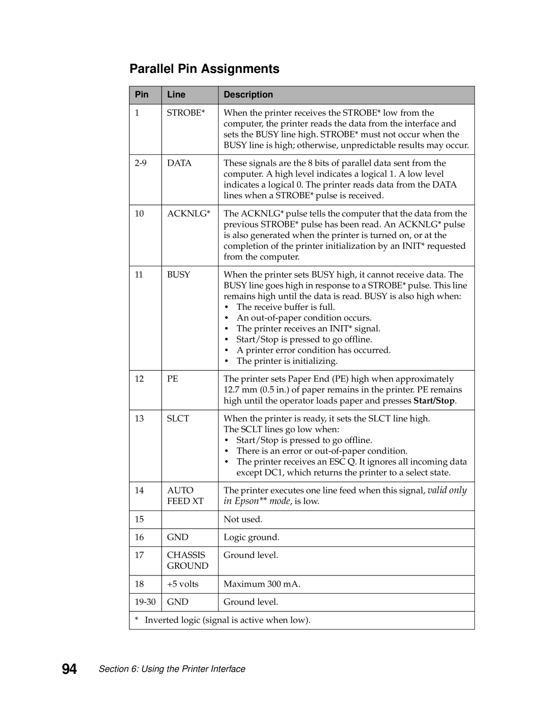
Parallel Pin Assignments
Pin Line Description
Timing
Init
Serial Interface
How to Connect the RS-232C Serial Interface
Universal Serial Bus Interface
Serial Interface Option
Serial Cable Pin Assignments RS-232C
Pin Signal Description
Following illustration shows the RS-232C serial cable
Serial Interface Cable RS-232C
Serial Communication Parameters RS-232C
Using an IBM AT Personal Computer RS-232C
Voltage Level Range
Data Transmission
100
Serial Data Frame Considerations RS-232C
Start and Stop Bits
101
Errors
Data Flow Control
102
XON/XOFF Protocol Timing
OS/2 1.2
Serial Computer Configuration Recommendations RS-232C
103
OS/2 2.0
104
Designing Draft and NLQ Characters
How Dots Are Added in NLQ Mode
248x Printers
105
106
Vertical Lines
107
Intersections of Vertical and Horizontal Lines
108
Diagonal Intersecting Horizontal Line
Downloading Characters
Designing Fast Draft Characters Designing NLQ II Characters
109
Downloading a Draft/NLQ Character Set
110
Initializing the Download Area
Part One Calculating Count 1, Count
Part Two Specifying the Download Data
111
Bit Bit Values Functions
112
Printable
Designing and Downloading the Draft/NLQ Copyright Symbol
113
114
115
Downloading an NLQ II Character Set
116
Bit Functions
117
Printable Data
118
119
120
249x Printers
Designing and Downloading Characters
Downloading a New Font
Font Descriptor Byte
121
Design Considerations
122
Download Sequence
123
124
Managing the Download Area
Lookup Table
Designing Monospaced Fast Draft Characters
125
126
MSB LSB
127
Use the following command to initialize the download area
Creating the Character Data
Downloading the Font Descriptor Byte
128
Downloading the Character Data
For more information about the Font Descriptor Byte, see
Downloading the Lookup Table Data
129
Creating the Lookup Table Data
Send the following lookup table information to the printer
130
Designing Monospaced Draft Characters
Printing the Character
131
LSB MSB
132
Initializing the Download Data
133
134
Designing Proportionally Spaced Characters
135
136
LSB MSB
137
Compressing the Character
138
139
Send the following lookup table example to the printer
140
Designing Enhanced Letter Quality Characters
141
142
143
1FFFF0
144
145
146
Barcodes
Barcode Function
Barcode Setup Command
Barcode Type Value
149
Is a space module Is a bar module
248x 249x
Is the space width adjustment factor
Value 248x space 249x space Module adjustment
151
Minimum Minimum v1 Printer Model Value Values
Data Transfer Command
Barcode Symbologies
153
N2 value Data character set
13, x0D
12, x0C
Character Hex
Valid EAN-13 command
155
Invalid EAN-13 command
N2 value
Valid EAN-8 command
157
Barcodes
159
To 255, x01 to xFF
X53
Valid Code 39 command
161
Invalid Code 39 command
Lowercase ’a’ is not a valid data character for Code
163
Interleaved 2of5
Valid Interleaved 2of5 command
165
Invalid Interleaved 2of5 command
11, x0B
Valid UPC-A command
167
N1 value b0=1
Character
Valid Postnet command
169
Postnet
’-’ dash is an invalid character for Postnet
171
To 255, x02 to xFF
Data character sets
Function Hex
Data character set a
173
Hex Character Code
Data character set B
175
Data character set C
Valid Code 128 command
Invalid Code 128 command
177
Valid Code 128 command using multiple character sets
179
X0005
181
Example
183
Space width adjustment = default
185
Barcodes
Code Pages
Code
Code Page 437G
189
Code
191
Code
Code Page 853T
193
Code
195
Code
197
Code
199
Code
201
Code
203
Code Command
Printing a Code
205
Output from the previous example is shown below
Set Font Global, ESC
207
248x Font Global IDs FGIDs Decimal, Hex and Byte Decimal
Gothic
209
249x Font Global IDs FGIDs Decimal, Hex and Byte Decimal
Pitch
211
Decimal Hex Code
213
Print Quality Decimal Hex
Interaction of Set Font Global and Set Print Quality
Select Fast Draft
Character Sets 1
215
Character Set
217
Code Pages
Glossary
Glossary
Numerics
Data flow control RS-232C Data frames serial Data packets
See serial adapter
Index
Index
Reader’s Comment Form
Business Reply Mail