Technical Reference
August
Edition August
Contents
TOC-2
TOC-3
Printer Specifications
TOC-4
TOC-5
PostScript Support
Introduction
Overview
PCL Emulation
Technical Reference Documentation Available in Hard Copy
Printer Specifications
Navigational Tips
Printing the File
Bibliography
Using the Operator Panel or MarkVision Professional
Using SmartSwitch
Selecting PCL Emulation
Using Your Software Program
Formatting
Printable Areas
Paper
Lexmark C510n Paper and Envelope Dimensions
Lexmark C510n
Envelope
Lexmark X422 Paper and Envelope Dimensions
Lexmark
Lexmark E230, E232, E234n, E330, E332n
Application
Print Area Menu Item
PCL
Edge
Font and Symbol Set Support for the Lexmark
Forward and Backward Compatibility Font Selection Commands
Forward and Backward Compatibility Modes for the Lexmark
Forward and Backward Compatibility Font Selection
OCR-A1
OCR-B1
Type 1 Fonts
PCL
Symbol Set Support for PCL Emulation Text Fonts
Selecting Symbol Sets for the Lexmark
Symbol Font Group Symbol Set PJL Value Set ID
Pifont
Psmath
MATH8
Mspubl
Non-Text PCL Emulation Symbol Sets
Symbol Symbol Set Set ID Fonts
OCR-A OCR-B
ISO PCL Emulation Symbol Sets
Symbol Set ID
ISO 6 Ascii
Font and Symbol Set Support for the Lexmark C510n
Courier 4099 Courier Italic Courier Bold
Forward and Backward Compatibility Font Selection
OCR-A1
Type 1 Fonts
PCL
Selecting Symbol Sets for the Lexmark C510n
11 Symbol Set Support for PCL Emulation Text Fonts
Psmath
12 Non-Text PCL Emulation Symbol Sets
13 ISO PCL Emulation Symbol Sets
Font and Symbol Set Support for the Lexmark E230, E232
Forward and Backward Compatibility Mode
Standard PCL Emulation Fonts
Specialty PCL Fonts
16 PCL Emulation Symbol Sets Latin
Selecting Symbol Sets for Lexmark E230, E232
PC850 PC858
Postnet Barcode C39 Narrow C39 Regular C39 Wide
PC852
WINL5 ISOL5 PC8TK
Typeface / Symbol Set PJL Value Symbol Set ID
18 PCL Emulation Symbol Sets Specials
15U 15Y 109Y 209Y 19M 579L 10L 14L
19 ISO PCL Emulation Symbol Sets
Symbol Set ID Symbol Set / Typeface
PCL
Standard PCL Emulation Fonts
PCL
Postnet Barcode Wingdings 31402 Symbol 16686
PCL
Specialty PCL Fonts
Selecting Symbol Sets for the Lexmark E234n, E330, and E332n
23 PCL Emulation Symbol Sets Latin
PCL
PCL
PCL
Wingdings Symbol SymbolPS ITC Zapf Dingbats
Symbol Set ID 17U 24Q 27Q 16U 18U
19L 26U 10N 10R 12R 13R 14R 12N 11G 10G 12G 14G
WINL2 ISOL2
PCL
PCL
OCR-A OCR-B
25 PCL Emulation Symbol Sets Specials
Symbol Set ID 15U 15Y 109Y 209Y 19M 579L 10L 14L
PCL
PCL
PCL
C39 Narrow C39 Regular C39 Wide
26 ISO PCL Emulation Symbol Sets
Control Codes
Command Structure
Commands
27 Control Codes
28 Description of Command Structure
Command Structure
Command Parameters
Element Description
Linking Commands
Command / Parameters Function / Result
PCL Emulation Commands
PCL Emulation Commands by Function
29 Job Control
Unit of Measure
Universal Exit Language UEL / Start of PJL
30 Page Control
Select Orientation
Set Universal Feed Direction
Set Universal Custom Name
Print Direction
Skip Perforation
Set Text Length
Set Output Bin
Set Horizontal Motion Index HMI
Duplex Page Side Selection
Text Scale Mode
Set Line Spacing Alternative Method
Set Page Length
31 Alphanumeric ID
32 Cursor Positioning
Vertical Cursor Position in PCL Units
Vertical Cursor Position in Rows
Vertical Cursor Position in Decipoints
Half Line-Feed
33 Font Selection
Select Underline Type Enable
Select Stroke Weight
Select Default Font
Underline Disable
34 User-Defined Symbol Set
35 Font Creation
36 Macros
37 Print Model
38 User-Defined Pattern
39 Rectangular Area Fill Graphics
Fill Rectangular Area
40 Raster Graphics
End Raster Graphics Version B
Set Raster Compression Mode
Transfer Raster Data by Row/Block
End Raster Graphics Version C
Raster Height Destination
Set Raster Configuration
Data
41 Color Extensions
Render Algorithm
Configure Image Data
Gamma Correction
Color Component One
42 Status Readback
44 Miscellaneous Commands
43 Picture Frame
45 Configuration Group
GL/2 Commands
Command / Parameter Command Name
46 Vector Group
47 Polygon Group
48 Character Group
49 Line and Fill Attributes Group
Syntax
Raster Compression Mode
Raster Image Graphics
Parameters
Uncoded Data
Example
Run-Length Encoded Data
Tagged Image File Format
Delta Row
Adaptive Compression
Scan Mode CountH,CountL Data
50 Adaptive Compression Control Strings
Zlib
Group 3 and Group 4 Raster Compression
Additional Compression Modes
Macros
Character Code Description Hex Code Decimal Code
PJL Command Notation
PJL Command Notation
ESC
Kernel Commands
Universal Exit Language Command
Enter Language Command
Comment Command
Job Separation Commands
JOB Command
Start = first
EOJ Command
Parameter
Beginning
Environment Commands and Variables
Environment Variable Categories
Categories
Default Command
SET Command
Values for devicefilename.filetype are Device
Initialize Command
Reset Command
Common Variables for Both Printer Languages
Variable Function Selections Factory Default
Common Variables for Both Printer Languages
Density
Cplock
ON, OFF
Duplex
Imageadapt
Holdtype
PUBLIC, Private Public
INTRAY2
Lang
Joboffset
ON, OFF, BETWEENJOBS, Betweencopies
DANISH, GERMAN, ENGLISH, SPANISH, French
Dinquire or Output Bin setting Inquire value
Parallel
Password
Powersave
SLOW, Fast
Timeout
Powersavetime
ON, OFF, Auto Resolution
QTY
Printer Unique Variables for Both Printer Languages
Printer Unique Variables for Both Printer Languages
Assign Type/Bin Dinquire or Bond setting Inquire value
Lcardstockoutbin
OPTIONALOUTBIN2, OPTIONALOUTBIN3 Disabled
Lcardstockweight
Lcardstocktexture
Lcoloredoutbin
Lcoloredweight
Lcoloredloading
Lcoloredtexture
SHORTEDGE, Longedge Shortedge
Lcustompaperheight
Lcustompaperfeed
LCUSTOMTYPE1LENGTH
LCUSTOMTYPE1TEXTURE
LCUSTOMTYPE1WEIGHT
LCUSTOMTYPE1OUTBIN
LCUSTOMTYPE2LENGTH
CUSTOMTYPE2
LCUSTOMTYPE2WEIGHT
LCUSTOMTYPE2NAME
LCUSTOMTYPE2OUTBIN
LABELS, CARDSTOCK, Envelope Cottonpaper LCUSTOMTYPE3NAME
LCUSTOMTYPE3WEIGHT
LCUSTOMTYPE3MEDIA
CUSTOMTYPE3
LCUSTOMTYPE4MEDIA
LCUSTOMTYPE4WEIGHT
LCUSTOMTYPE4LOADING
LABELS, CARDSTOCK, Envelope Cottonpaper LCUSTOMTYPE4NAME
LCUSTOMTYPE5MEDIA
LCUSTOMTYPE5LENGTH
LCUSTOMTYPE5LOADING
LABELS, CARDSTOCK, Envelope Cottonpaper LCUSTOMTYPE5NAME
LCUSTOMTYPE6LOADING
LCUSTOMTYPE5WEIGHT
LCUSTOMTYPE6LENGTH
LCUSTOMTYPE6MEDIA
Assign Type/Bin Dinquire or Envelope setting Inquire value
PRINT, DONOTPRINT, Printerror
Lenvelopeweight
Lfaxresolution
Lenvelopetexture
Assign Type/Bin Dinquire or Glossy setting Inquire value
Limageorientation
Otherenvelope Ljamrecovery
Limageenhancetype
DONOTROTATE, Rotatepaper Donotrotate
Assign Type/Bin Dinquire or Labels setting Inquire value
Lletterheadtexture
Lletterheadweight
Lletterheadoutbin
Lmanualcolorrgbtext
Lmanualenvelopetype
OFF, VIVID, VIVIDCMYK, USCMYK, Eurocmyk Uscmyk US Image
Lmanualenvelopesize
Lmanualpapersize
AUTO, SHORTEDGE, Longedge Auto Lnpap
Lmultipageprint
Lmultipageview
LOPTIONALOUTBIN1NAME
OUTBIN6
Loutbinconfig
LOPTIONALOUTBIN6NAME
LOPTIONALOUTBIN7NAME
Overflow Bin Dinquire or Setting Inquire value
Assign Type/Bin Dinquire or Plain setting Inquire value
Ppds
Lppds
Lppdsformlines
Lppdslinesperinch
Lpreprintedtexture
Lpreprintedweight
Lpreprintedoutbin
Lprintbuffer
QUICKPRINT, NORMAL, Presentation Normal
Lreset
Lprintquality
GRAPHICS, IMAGES, 1200IMAGEQ, Inksaver NORMAL, Best Lpunch
Lstrokewidth
ON, OFF, AUTO, FRONT, BACK, DUAL, 0, 1 Lstaplesemptyalarm
Lstandardoutbinname
Lstaple
Ltransparencytexture
Ltransparencyweight
Ltransparencyoutbin
LTRAY1SENSEDTYPE
LTRAY4SENSEDTYPE
LTRAY3SENSEDTYPE
LETTERHEAD, PREPRINTED, Colored CUSTOMTYPE3
LETTERHEAD, PREPRINTED, Colored CUSTOMTYPE4
LTRAY3PAPERTYPE
Lusdefaults
LTRAY2PAPERTYPE
LTRAY4PAPERTYPE
Common Variables for PCL Emulation
Common Variables for PCL Emulation
Printer Unique Variables for PCL Emulation
Printer Unique Variables for PCL Emulation
LASSIGNTRAY3
LASSIGNTRAY1
LASSIGNTRAY2
LASSIGNTRAY4
Common Variables for PostScript Emulation
Variable Function Selections Default
Common Variables for PostScript Emulation
Factory
Printer Unique Variables for PostScript Emulation
Printer Unique Variables for PostScript Emulation
Printer Unique Lresource Variables
ON, OFF Lpsfontpriority
Printer Unique Lresource Variables
Dinquire Command
Status Readback Commands
Response Syntax
Echo Command
10 Info Category Parameter Values
Info Command
Category Values Description
Info Config Response Syntax An Example
Manual Feedcrlf
Inquire Command
Ustatus Command
11 Ustatus Unsolicited Status Variable Values
Ustatusoff Command
Ustatus Variable Value Description
12 PJL Information Messages
Status Message Format
Information Messages
Printer State Status Code Display String Online Status
11xyy
13 PJL Messages for Auto-Continuable Conditions
Auto-Continuable Conditions
Status Printer State Code Display String Online Status
Intervention required 30018 Serial 1 Port Disabled
Intervention required 30075 Scheduled Maintenance
Intervention required 32002 Disk Full
Attendance Conditions
14 PJL Message for Attendance Conditions
Cartridge life warning Intervention required 40021
Print cartridge missing Intervention required 40022
Intervention required 40037
Opmsg
Stmsg
Operator Intervention Paper Handling
Load staples
15 PJL Messages for Paper Handling
Value Tray
16 Tray Codes
17 Media Size Codes
YY Value Media Size
18 Output Bin Codes
Operator Intervention Paper Jams
WW Value Output Bin
19 PJL Messages for Paper Jams
Intervention required 4232x
Intervention required 4253w
Intervention required 4281w
Service Errors
Device Attendance Commands
Rdymsg Command
Opmsg Command
Stmsg Command
Lbeep Command
Unique PJL Commands
Lportrotate Command
20 Lprint testpage Commands
Lprint Commands Information Pages
Lescapechar Command
Testpage Value Description
PJL
21 Lfax Phonenumber number Values
Lfax Phonenumber Command
Character Description
Ldownloadtarget Command
File Commands for Flash or Disk
22 Variables for Flash and Disk File and Password Commands
Parameter Syntax Description
MAC5
Lopenfile Command
Lclosefile Command
Lreadfile Command
Lwritefile Command
Lrunfile Command
Lformat Command
Lrenamefile Command
Ldeletefile Command
Ldefrag Command
Password Protection for a File
File and Device Protection Commands
Protecting a File or Device
Password for an Entire Device
Unlocking a Protected File or Device
Re-Locking a Protected File or Device
Unlocking a Protected File or Device for the Current Job
Recovering Lost Passwords
PostScript Emulation
Selecting PostScript Emulation
Using Your Software Program
Portrait
Lexmark C510n
Logical Page Size
Lexmark C510n PostScript 3 Emulation Printable Area
Lexmark
Lexmark X422 PostScript 3 Emulation Printable Area
Lexmark E230, E232, E234n, E330, E332n
PostScript Emulation Fonts for the Lexmark
Backward compatibility
Lexmark Optra S Drivers
Forward compatibility
If you need the Lexmark Optra S driver for Use
PostScript Emulation Fonts for the Lexmark C510n
TimesNewRomanPS-BoldItalicMT
Lexmark Optra S Drivers
PostScript
GoldSansMM NewCenturySchlbk-Roman
Command Format
Supplemental Operators
Nameofoperator
Error bold font
Paper Size Support
They set PageSize Policy to
Paper Sizes Supported
Currentuniversalsize
Error stackoverflow
Errors rangecheck, stackunderflow, typecheck
Ignoresize
Paper Tray Support
Error rangecheck, stackunderflow, typecheck
Setuniversalsize
Where x y are the PageSize in points
Tray Selected with Tray Operators
Manualfeed
Papertray
Setpapertray
Envelope Size Support
Envelope Sizes Supported
10 Literal Names Supported
Envelope Tray Support
11 Envelopetray Operator Selections
Buildtime
Supplemental Operator Summary
Appletalktype
Byteorder
Currentfilenameextend
Checkpassword
Errors stackunderflow, typecheck
Currentmanualduplexmode
Defaulttimeouts
Deletefile
Devcontrol
12 devcontrol Operator Parameters
Errors invalidaccess, stackunderflow, undefinedfilename
13 Unsuccessful devcontrol Parameter Error Codes
Errors invalidaccess, rangecheck, typecheck
Devdismount
Devforall
Devformat
Devmount
Devstatus
Error typecheck
Diskonline
Displayoperatormsg
Diskstatus
Doidlefonts
Doprinterrors
Dojamrecovery
Doret
Dosysstart
Dostartpage
Duplexer
Duplexmode
Enginesync
Filenameforall
Errors ioerror, stackoverflow, stackunderflow, typecheck
File
Fileposition
Hardwareiomode
Firstside
Fontnonzerowinding
Idlefonts
Initializedisk
Jobname
Jobsource
Jobtimeout
LPRB% LPRC%
Newsheet
Manualfeedtimeout
Errors stackoverflow, undefined
Pagecount
Printername
Pagesprinted
Product
PS3fonts
PS2fonts
Quiet
Realformat
Ramsize
Renamefile
Resolution
Revision
Sccbatch
Errors rangecheck, stackoverflow, stackunderflow, typecheck
Stop Bits Data Style Flow Control Parity
Sccinteractive
Setdefaulttimeouts
Errors invalidaccess, rangecheck, stackunderflow, typecheck
Setcoverpage
Errors invalidaccess, stackunderflow, typecheck
Setdojamrecovery
Setdoprinterrors
Setdoidlefonts
Setdoret
Setdostartpage
Setdosysstart
Errors configurationerror, stackunderflow, typecheck
Setduplexmode
Setethernetaddress
Setenginesync
Setfilenameextend
Sethardwareiomode
Error unmatchedmark
Setfileposition
Setidlefonts
Error stackunderflow, typecheck
Setjobtimeout
Setmanualduplexmode
Setprintername
Errors invalidaccess, limitcheck, stackunderflow, typecheck
Setquiet
Error stackunderflow
Setresolution
Setsccbatch
Setsoftwareiomode
Errors stackunderflow, typecheck, invalidaccess, rangecheck
Setsccinteractive
Settumble
Softwareiomode
Setuserdiskpercent
Tumble
Errors stackoverflow, invalidaccess
Waittimeout
Userdiskpercent
Key Type Definition
Device Parameters
14 Page Device Parameters
TonerSaver, PictureGrade, ImageEnhancement, PrintDarkness
PostScript
Information on PageSize, see
Menu item. The following values are supported
Key Source
InputAttributes. The allowable values are
Infinite wait or no timeout
Horizontal Vertical
Rows Columns
Reverse Horizontal Reverse Vertical
Orientation specified by the PageSize parameter
Setpagedevice operator
Findcolorrendering operator
DefaultPageSizePolicy key in the DeviceRenderingInfo
Generate a configurationerror
Power Saver menu item
SlipSheetDetails Dictionary
Printer. Supported values are
User Parameters
Interpreter Parameters
15 PostScript Emulation User Parameters
HalftoneMode Integer
Setcolorscreen, and sethalftone are not affected
Printer for a specific job
System Parameters
16 PostScript Emulation System Parameters
Same as CurInputDevice
Also transmitted to the host over the communications
InstalledRam
Read-only Total amount of memory in bytes installed
To change the values of device parameters
Device Parameters
17 PostScript Emulation Device Parameters
PCL Ppds
PostScript
Serial RS-232/RS-422menu item. Supported values are
PostScript
PostScript
DelayedOutputClose Boolean
PostScript
PostScript
PostScript
PostScript
PostScript
PostScript
PostScript
PostScript
100
Device Parameters for the Parameters Device %Engine%
Darkness Value Print Darkness Toner Saver Setting Value
Print Darkness and Toner Saver Setting
Print Darkness Setting
CalendarD%
Device Parameters for the Parameters Device %Console%
Device Parameters for the IODevice Device %disk1%
LogicalSize
Device Parameters for the IODevice %flash1%
104
105
Device Parameters for the IODevice %rom%
Tagged Binary Not Active
Status and Error Messages
Tagged Binary Active
Key Value Description
Status Messages
18 Status Message Keys and Value Descriptions
USB
Handleerror
Unsolicited Messages
Switching Languages
SmartSwitch
Setting SmartSwitch for Different Interfaces
Printer Job Language
Sniffing
Flash Memory and Disk
Resource Data Collection Download Target
Viewing the Contents of Flash Memory and Disk
Example of Directory
Part Name
Part Number
Size
Password Protection
Description
Rewriting the Flash Content
File Naming Conventions
Accessing Files with PostScript Emulation
Device Names
Filenames
Filename Extensions
To add the .data extension automatically again, issue
Device Search Order
Initializedisk Devformat
Device Performance Retrieval Speeds
Performance
Job Buffering
Device Retrieval Speed Write
Creating a Partition
Enabling Job Buffering
Recovering from a Power Loss
Disabling Job Buffering
Noise Emission Levels
Airflow Requirement
Noise Emission Levels
Printer Electrical Specifications
Electrical Specifications
Power Requirements
Power Requirements
Printer Model C510 X422 E230 State 100 120 230V
Printer Model E33x E232 State 100 120 230
Clearance Requirement Specifications
Physical Specifications
Printer Physical Specifications
Clearance Requirements
Environmental Conditions
Altitude Specifications
Atmospheric Pressure
Time to Print the First
Power On to Ready State Time Period
Power On to Ready State Time Period
10 Time to Print the First
Printer Interfaces
Setting Up the Communications Port
Setting Up the Communications Port Using Windows 95/98/Me
Setting Up the Communications Port Using Windows NT
Interfaces
Interfaces
Deciding Which Interface to Use
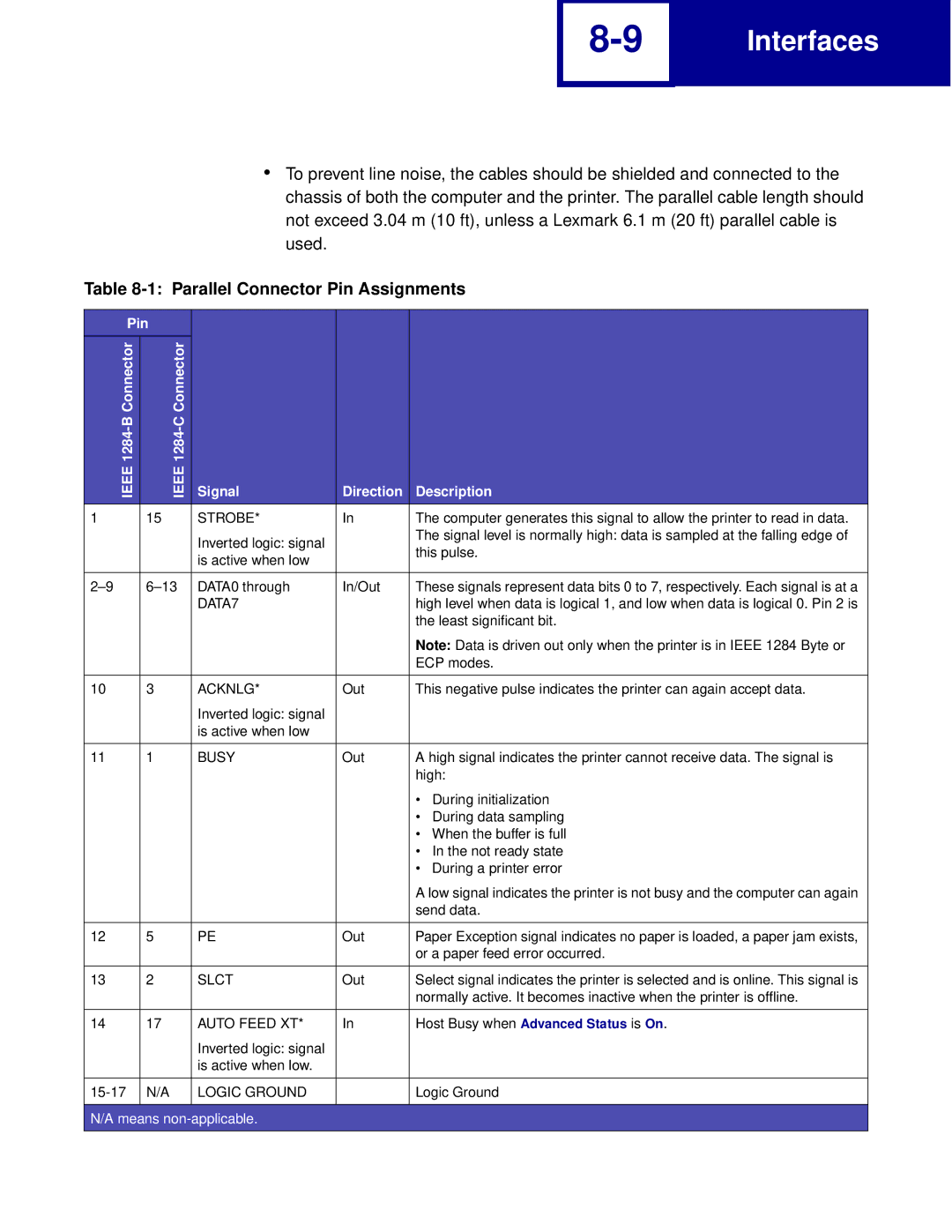
Parallel Interface
Computer to Printer
Optional Parallel Connector
Standard Parallel Connector
Parallel Connector Pin Assignments
Pin Connector
Parallel Connector Pin Assignments
Signal Direction Description
Host Logic High
Error
VCC
GND
Standard Parallel Connector
Using the INIT* Signal to Initialize
Computer-to-Printer Communications
Printer Side Pin Connector 1284-B Computer
Ieee 1284-C Ieee 1284-A
Printer Computer Side 36-Pin 25-Pin Connector 1284-C
Standard Protocol Data Transfer Sequence
Typical Parallel Interface Timings
Fastbytes Protocol Data Transfer Sequence
Time Name Minimum/Maximum
Printer-to-Computer Communication Advanced Status
Fastbytes Timing Sequence
Parallel Mode
Signal Descriptions
Strobe Receiver for the Lexmark C510
AUTOFD* Receiver for the Lexmark C510
Data 1-8 Signal Driver/Receivers for the Lexmark C510
ACKNLG*, ERROR*, SLCT, PE Drivers for the Lexmark C510
Busy Driver and INIT* Receiver for the Lexmark C510
SLCTIN* Receiver for the Lexmark C510
Serial Interface
Dedicated Serial Connector Pin Assignments RS-232C
Using the RS-232C Serial Interface
How to Connect the RS-232C Serial Interface
Pin Signal Direction Description
DSR
RTS
CTS
DTR
To 25 Pin Cable Adapter Such as IBM 6450242 10
Serial Communication Parameters RS-232C
Voltage Level Range
Start and Stop Bits
Data Flow Control
Serial Link All Protocols with Honor DSR On
Protocol RS-232C
Serial Link All Protocols with Honor DSR Off
DTR and DTR/DSR Protocol Timing RS-232C
XON/XOFF Protocol Timing RS-232C
Serial Errors
Serial Computer Configuration Recommendations RS-232C
How to Connect the RS-422 Serial Interface
Using the RS-422 Serial Interface
RS-232C Port Compatibility
Dedicated Serial Connector Pin Assignments RS-422
Serial Cable Pin Assignments RS-422
Serial Communication Parameters RS-422
Voltage Level
Data Flow Control Protocol
XON/XOFF Protocol Timing RS-422
Serial Computer Configuration Recommendations RS-422
Network Support
Serial Network Memory Size Parallel Buffer Size LocalTalk
Input Buffer
Input Buffer Sizes in Bytes
Fax
Command Function
Table A-1 PCL Emulation Commands
C510n X422
Size
Primary Font Symbol Set
Logical Operation
End Raster Graphics Version B
Table A-2 GL/2 Commands
PCL Support
PCL Support
PCL Support
Table B-1 Common Variables for Both Printer Languages
Printer Model Variable Name C510n X422
E230, E232, E234n, E330, E332n
Variable Name C510n X422
Resourcesavesize RET Timeout Username WIDEA4
Auto
PJL Support
PJL Support
PJL Support
Lpicturegrade Lplainlength
PJL Support
LTRAY3PAPERTYPE LTRAY4PAPERTYPE
Table B-4 Printer Unique Variables for PCL Emulation
LTRAY5PAPERTYPE LTRAY1RENUMBER LTYPE1FONTS Lusdefaults
Table B-3 Common Variables for PCL Emulation
Fontnumber Fontsource Pitch Ptsize Symset
Table B-6 Printer Unique Variables for PostScript Emulation
Jamrecovery Prtpserrs Adobembt
Table B-5 Common Variables for PostScript Emulation
Lpicturegrade Lpsfontpriority
Table B-9 Ustatus Unsolicited Status Variables
Table B-8 Status Readback Commands
Table B-7 Printer Unique Lresource Variables
Ldescription Lrwlock Lwlock
E230, E232 E234n, E330, E332n
Table B-10 PJL Messages for Auto-Continuable Conditions
C510n Message Status Code Return String X422
Intervention Required 30018
Intervention Required 30076
Intervention required 32015
Table B-11 PJL Messages for Attendance Conditions
Tray Size Sense Error Intervention Required 40021
Intervention Required 40027
Black Photo Dev Life Warning Intervention Required 40038
Intervention Required 40049 Stmsg message
Table B-12 PJL Messages for Paper Handling
41xxy
Status Code Return String C510n X422
Table B-13 PJL Messages for Paper Jams
Message Status Code
C510n Message Status Code X422
PJL Support
PJL Support
PJL Support
Command
Table B-14 Service Errors
Table B-16 Lexmark Unique PJL Commands
Table B-15 Device Attendance Messages
Table B-17 File and Device Protection Commands
Table C-1 Supplemental Operators
Operator Name
PostScript Support
PostScript Support
Table C-2 Page Device Parameters
Key
SubstituteSize Type
MediaColor MediaPosition
PageSize Policies PolicyNotFound PolicyReport
Default C510n X422
Table C-3 User Interpreter Parameters
Table C-4 System Interpreter Parameters
X422 Key
C510n Device X422 E230 E232 E234 E234n E330 E332n
Table C-5 Devices Supported
USBA% USBB% USBC% USBD%
Device C510 C510n X422 E230 E232 E234 E234n E330 E332n
LPRA% LPRB% LPRC% LPRD%
Table C-6 Device Parameters
Supported Printer Model Not Supported C510n X422
PSSmartSwitch RobustXon SerialMode StopBits Type
PortLocation PSSmartSwitch Type
PostScript Support
PostScript Support
Enabled Filtering HasNames Interpreter PortLocation Type
Device Parameters for the Parameters Device %Engine%
Device Parameters for the Parameters Device %Console%
Device Parameters for the Parameters Device %flash1%
Table C-7 PostScript Commands Message Keys
Device Parameters for the Parameters Device %rom%
Index
See disk
Index
Index
Index
MarkVision Professional
Index
Index
Index
Comment
Lcoloredlength
Lnpap
LTRAY1RENUMBER
Slctin
Index