Name and Functions of Wireless TV Parts
Rear view of the wireless TV


1
2
4
3
Wireless transmission unit


2
1
3
Rear view of the transmission unit
4 |
5 |
6 |
7 |
8 |
9 |
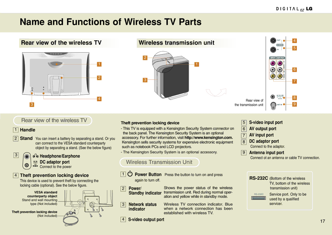
Rear view of the wireless TV
1Handle
2Stand You can insert a battery by separating a stand. Or you
can connect to the VESA standard counterparty object by separating a stand. (See the below figure)
3 | Headphone/Earphone |
DC adaptor port
Connect to the power
4Theft prevention locking device
This device is used to prevent theft by connecting the locking cable (optional). See the below figure.
VESA standard counterparty object
Stand and wall mounting type (Not included)
Theft prevention locking device
(Not included)
Theft prevention locking device
-This TV is equipped with a Kensington Security System connector on the back panel. The Kensington Security System is an optional
accessory. For further information, visit http://www.kensington.com. Kensington sells security systems for expensive electronic equipment such as notebook PCs and LCD projectors.
- The Kensington Security System is an optional accessory.
Wireless Transmission Unit
1 | Power Button | Press the button to turn on and press |
| again to turn off. |
|
2 | Power/ | Shows the power status of the wireless |
| Standby indicator | transmission unit. Red during normal oper- |
|
| ation and yellow while in standby mode. |
3Network status Wireless TV connection indicator. Blue
indicator | when a network connection has been |
| established with wireless TV. |
5
6
7
8
9
AV output port
AV input port
DC adaptor port
Connect to the adaptor.
Antenna input port
Connect ot an antenna or cable TV connection.
Service port. Only to be used by a qualified servicer.
4
17 | |
|