Installation

13.Smoke detector alarm connections. Field-supplied 24V. Class 1 wiring to remote alarm circuits. Factory-wired contacts from optional smoke detector are #91 -comm., #92-NO, and #93-NC.

14.Common alarm connection. Field-supplied 24V. Class 1 wiring to common alarm terminals 75 + 76 (and optional 94 + 95, and 96 + 97), which are factory connected to common alarm relay (R3).

15.Heat rejection connection. Field-supplied 24V Class 1 wiring to interlock heat rejection from pigtails 70 + 71 which are factory connected to compressor side switch (self-contained units only and to GLYCOOL relay (R5), GLYCOOL units only).

16.Reheat and Humidifier Lockout. Optional emergency power lockout of reheat and/or humidifier: connections provided for remote 24V AC source.

17.Main Fan Auxiliary Switch. Optional main fan auxiliary side switch. Terminals located in field wiring compartment for remote indication that the evaporator fan motor/unit is on. Field to connect 24V maximum.

18.Optional Condensate Alarm (Dual Float Condensate Pump only). Relay terminals located in field wiring compartment for remote indication.

*Located inside unit on top for Upflow and on base for Downflow.

2.7Balancing the Air Distribution

2.7.1Under-Floor Discharge Systems

The systems are designed for constant air delivery, therefore any unusual restrictions within the air circuit must be avoided. For under-floor air distribution, observe the following guidelines:

Select the air supply grilles and perforated panels for the raised floor to ensure minimum loss of pressure in the circuit. Air volume dampers on grilles, which extend several inches below the sur- face of the raised floor, are usually detrimental to airflow.

Consideration of the height of the damper on the grille in conjunction with the floor height will determine whether this type of grille may be used.

The grilles used in raised floors vary in size, the largest being approximately 18" x 6"

(457 x 152 mm). A larger grille size would be detrimental to the structural capacity of the raised floor panel. An 18" x 6" (457 x 152 mm) heavy duty, pencil-proof type grille typically has 56 square inches (0.036 m2) of free area.

Perforated panels are available from various manufacturers of raised floors. These panels are usually 2' x 2' (610 x 610 mm) square and have a nominal free area of approximately 108 to 144 square inches (0.07 to 0.09 m2). Use caution in selecting perforated panels as some manufacturers have only 36 to 40 square inches (0.023 to 0.026 m2) of free area, requiring four times as many panels.

Avoid floor elevations below 7-1/2" (190.5 mm), loosely installed flooring systems, and below-floor obstructions such as: electrical wiring chases, unusually long electronic system cables, or piping clusters.

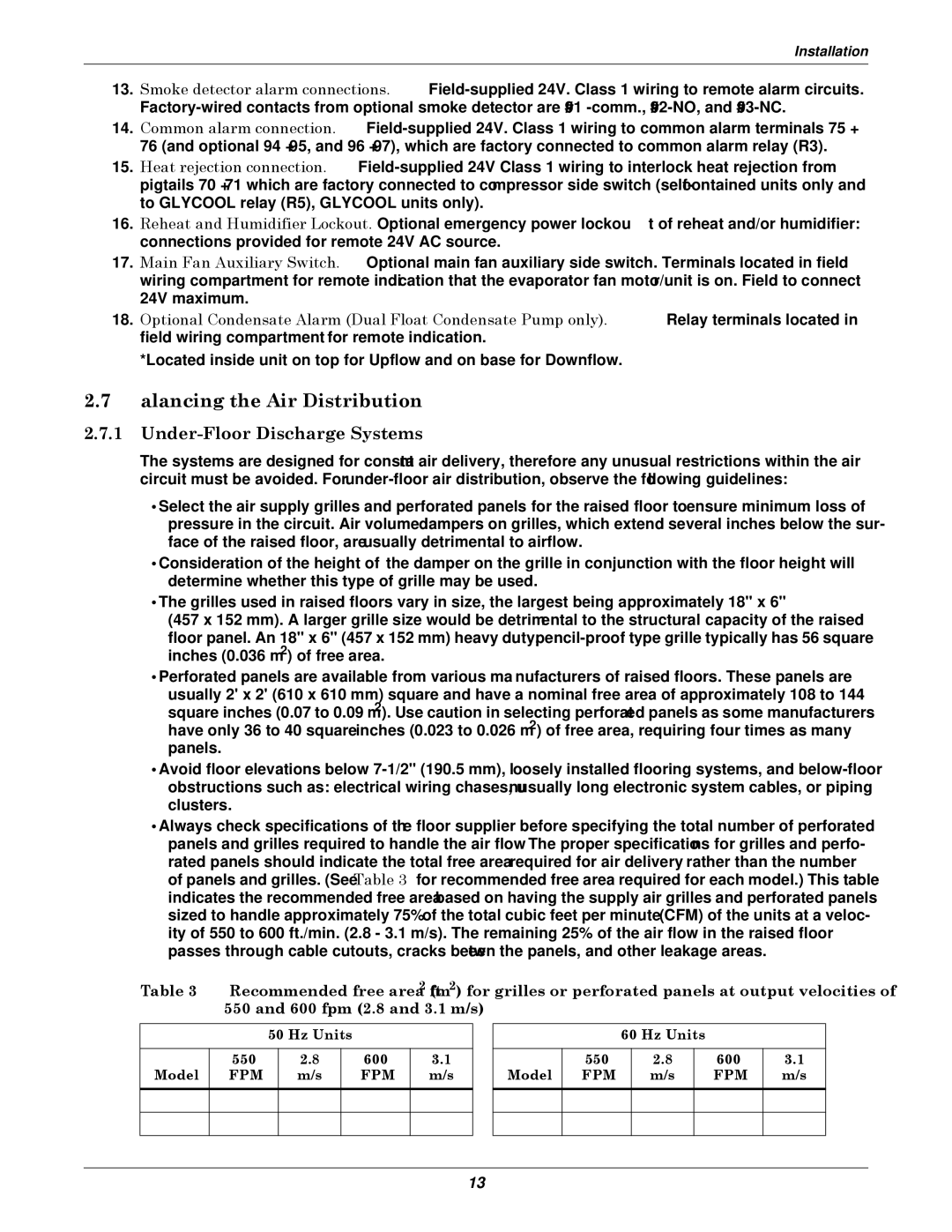
Always check specifications of the floor supplier before specifying the total number of perforated panels and grilles required to handle the air flow. The proper specifications for grilles and perfo- rated panels should indicate the total free area required for air delivery rather than the number of panels and grilles. (See Table 3 for recommended free area required for each model.) This table indicates the recommended free area based on having the supply air grilles and perforated panels sized to handle approximately 75% of the total cubic feet per minute (CFM) of the units at a veloc- ity of 550 to 600 ft./min. (2.8 - 3.1 m/s). The remaining 25% of the air flow in the raised floor passes through cable cutouts, cracks between the panels, and other leakage areas.

Table 3 Recommended free area ft2 (m2) for grilles or perforated panels at output velocities of 550 and 600 fpm (2.8 and 3.1 m/s)

50 Hz Units


550

2.8

600

3.1

Model

FPM

m/s

FPM

m/s


3 Ton

2.5

(0.01)

2.3

(0.01)


5 Ton

3.5

(0.02)

3.3

(0.02)


60 Hz Units


550

2.8

600

3.1

Model

FPM

m/s

FPM

m/s


3 Ton

2.5

(0.01)

2.3

(0.01)


5 Ton

3.8

(0.02)

3.5

(0.02)


13

Page 19
Image 19
Liebert 3000 installation manual Balancing the Air Distribution, Under-Floor Discharge Systems, Hz Units 550 600 Model

3000 specifications

The Liebert 3000 is a cutting-edge power protection solution designed to provide reliable and efficient backup power for critical applications. This uninterruptible power supply (UPS) system is engineered to safeguard sensitive electronic equipment from power disturbances, ensuring uninterrupted operations in data centers, telecommunications, and industrial environments.

One of the standout features of the Liebert 3000 is its high-efficiency design. With an efficiency rating of up to 94%, the system minimizes energy loss, resulting in lower operational costs and a reduced carbon footprint. This is particularly important in today's environmentally conscious climate, as organizations strive to meet sustainability goals while maintaining top-tier performance.

The Liebert 3000 employs advanced technologies to enhance its functionality. It incorporates online double-conversion technology, which provides a continuous supply of clean and regulated power. This technology ensures that connected loads receive stable voltage and frequency, shielding them from voltage spikes, sags, and outages. Additionally, the UPS offers features such as automatic battery testing, which helps ensure peak battery performance and reliability.

Another key characteristic of the Liebert 3000 is its modular design, allowing for flexible scalability. This means that organizations can easily expand the capacity of their UPS system as their power needs grow, without the need for extensive system overhauls. The modular architecture also facilitates simplified maintenance and reduces downtime, as individual modules can be serviced without interrupting power to the critical load.

The system is equipped with comprehensive monitoring and management capabilities. The Liebert 3000 provides real-time data on power usage, battery status, and system performance, enabling facility managers to make informed decisions and proactively address potential issues. The integration of remote management tools allows for seamless monitoring from anywhere, providing peace of mind for operators.

Overall, the Liebert 3000 combines high efficiency, advanced technology, and flexible design to deliver a robust power protection solution. Its reliability and performance make it a preferred choice for organizations seeking to protect their critical infrastructure while enhancing operational efficiency and sustainability. As businesses continue to rely on technology for their everyday operations, the Liebert 3000 stands out as a dependable safeguard against the uncertainties of power quality.