Site Preparation and Installation
2.5.3Piping Connections
Details for refrigerant
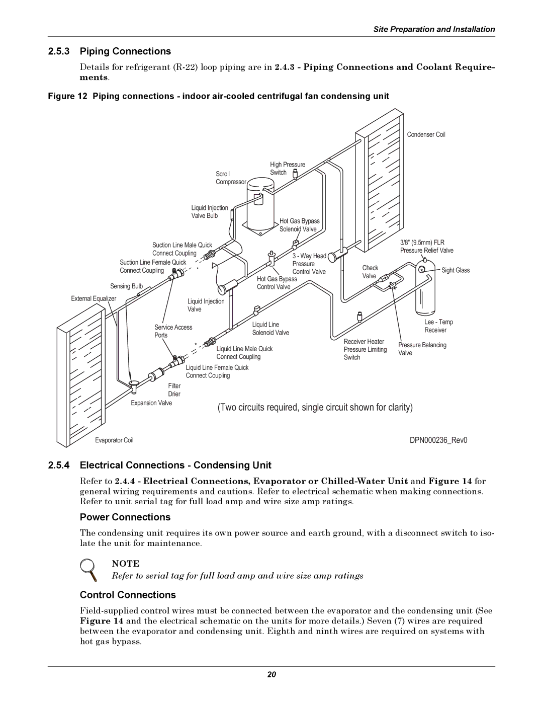
Figure 12 Piping connections - indoor air-cooled centrifugal fan condensing unit
|
|
|
|
| Condenser Coil |
|
|
| High Pressure |
|
|
|
| Scroll | Switch |
|
|
|
| Compressor |
|
|
|
| Liquid Injection |
|
|
| |
| Valve Bulb | Hot Gas Bypass |
|
| |
|
|
|
|
| |
|
|
| Solenoid Valve |
|
|
Suction Line Male Quick |
|
|
| 3/8" (9.5mm) FLR | |
|
|
| Pressure Relief Valve | ||
Connect Coupling |
| 3 - Way Head |
| ||
|
|
| |||
Suction Line Female Quick | * |
| Pressure | Check | Sight Glass |
Connect Coupling |
| Control Valve | |||
Sensing Bulb |
|
| Hot Gas Bypass | Valve |
|
|
| Control Valve |
|
| |
External Equalizer | Liquid Injection |
|
|
| |
| Valve |
|
|
|
|
Service Access |
| Liquid Line |
| Lee - Temp | |
|
| Receiver | |||
| Solenoid Valve |
| |||
Ports |
|
|
| ||
|
| Receiver Heater |
| ||
|
|
| Pressure Balancing | ||
| * | Liquid Line Male Quick | |||
| Pressure Limiting | ||||
|
| Valve | |||
|
| Connect Coupling | Switch | ||
|
|
| |||
Liquid Line Female Quick
Connect Coupling
Filter
Drier
Expansion Valve
(Two circuits required, single circuit shown for clarity)
Evaporator Coil | DPN000236_Rev0 |
2.5.4Electrical Connections - Condensing Unit
Refer to 2.4.4 - Electrical Connections, Evaporator or
Power Connections
The condensing unit requires its own power source and earth ground, with a disconnect switch to iso- late the unit for maintenance.
NOTE
Refer to serial tag for full load amp and wire size amp ratings
Control Connections
20