Microprocessor Control
Test Micro
By selecting this function, the microcontroller will perform a self test lasting approximately 10 sec- onds. When the test is complete, the display will show the ROM checksum, ROM part number, and firmware revision number.
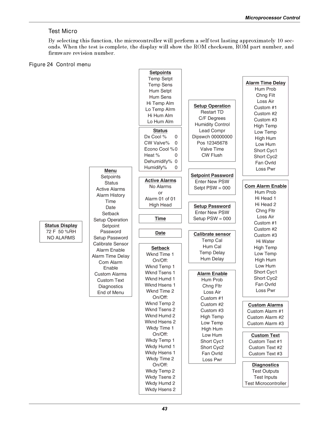
Figure 24 Control menu
Setpoints
Temp Setpt
Temp Sens
Hum Setpt
Hum Sens
Hi Temp Alm
Lo Temp Alrm
Hi Hum Alm
Lo Hum Alm
Status |
|
Dx Cool % | 0 |
CW Valve% | 0 |
Econo Cool % 0 | |
Heat % | 0 |
Dehumidify% | 0 |
Humidify% | 0 |
Setup Operation
Restart TD
C/F Degrees
Humidity Control
Lead Compr
Dipswch 00000000
Pos 12345678
Valve Time
CW Flush
Alarm Time Delay
Hum Prob
Chng Filt
Loss Air
Custom #1
Custom #2
Custom #3
High Temp
Low Temp
High Hum
Low Hum
Short Cyc1
Short Cyc2
Fan Ovrld
Loss Pwr
Status Display
72 F 50 %RH
NO ALARMS
Menu
Setpoints
Status
Active Alarms
Alarm History
Time
Date
Setback
Setup Operation
Setpoint
Password
Setup Password
Calibrate Sensor
Alarm Enable
Alarm Time Delay
Com Alarm
Enable
Custom Alarms
Custom Text
Diagnostics
End of Menu
Active Alarms
No Alarms
or
Alarm 01 of 01
High Head
Time
Date
Setback
Wknd Time 1
On/Off:
Wknd Temp 1
Wknd Tsens 1
Wknd Humd 1
Wknd Hsens 1
Wknd Time 2
On/Off:
Wknd Temp 2
Wknd Tsens 2
Wknd Humd 2
Wknd Hsens 2
Wkdy Time 1
On/Off:
Wkdy Temp 1
Wkdy Humd 1
Wkdy Hsens 1
Wkdy Time 2
On/Off:
Wkdy Temp 2
Wkdy Tsens 2
Wkdy Humd 2
Wkdy Hsens 2
Setpoint Password
Enter New PSW Setpt PSW = 000
Setup Password
Enter New PSW Setup PSW = 000
Calibrate sensor
Temp Cal
Hum Cal
Temp Delay
Hum Delay
Alarm Enable
Hum Prob
Chng Fltr
Loss Air
Custom #1
Custom #2
Custom #3
High Temp
Low Temp
High Hum
Low Hum
Short Cyc1
Short Cyc2
Fan Ovrld
Loss Pwr
Com Alarm Enable
Hum Prob
Hi Head 1
Hi Head 2
Chng Fltr
Loss Air
Custom #1
Custom #2
Custom #3
Hi Water
High Temp
Low Temp
High Hum
Low Hum
Short Cyc1
Short Cyc2
Fan Ovrld
Loss Pwr
Custom Alarms
Custom Alarm #1
Custom Alarm #2
Custom Alarm #3
Custom Text
Custom Text #1
Custom Text #2
Custom Text #3
Diagnostics
Test Outputs
Test Inputs
Test Microcontroller
43
