Section TOC
Master TOC
TROUBLESHOOTING AND REPAIR | ||
|
|
CONTROL PC BOARD
REMOVAL AND REPLACEMENT PROCEDURE (Continued)
Return to
Section TOC
Return to
Master TOC
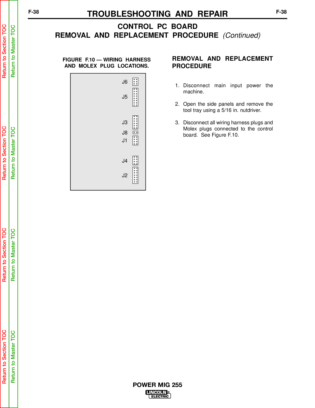
FIGURE F.10 — WIRING HARNESS AND MOLEX PLUG LOCATIONS.
J6
J5
J3
J8
J1
REMOVAL AND REPLACEMENT PROCEDURE
1.Disconnect main input power the machine.
2.Open the side panels and remove the tool tray using a 5/16 in. nutdriver.
3.Disconnect all wiring harness plugs and Molex plugs connected to the control board. See Figure F.10.
Return to
Return to Section TOC
Return to Section TOC
Return to
Return to Master TOC
Return to Master TOC
J4
J2