Return to Section TOC
Section TOC
Return to Master TOC
Master TOC
TROUBLESHOOTING & REPAIR | |||
| STATIC SCR RECTIFIER ASSEMBLY TEST (continued) |
| |
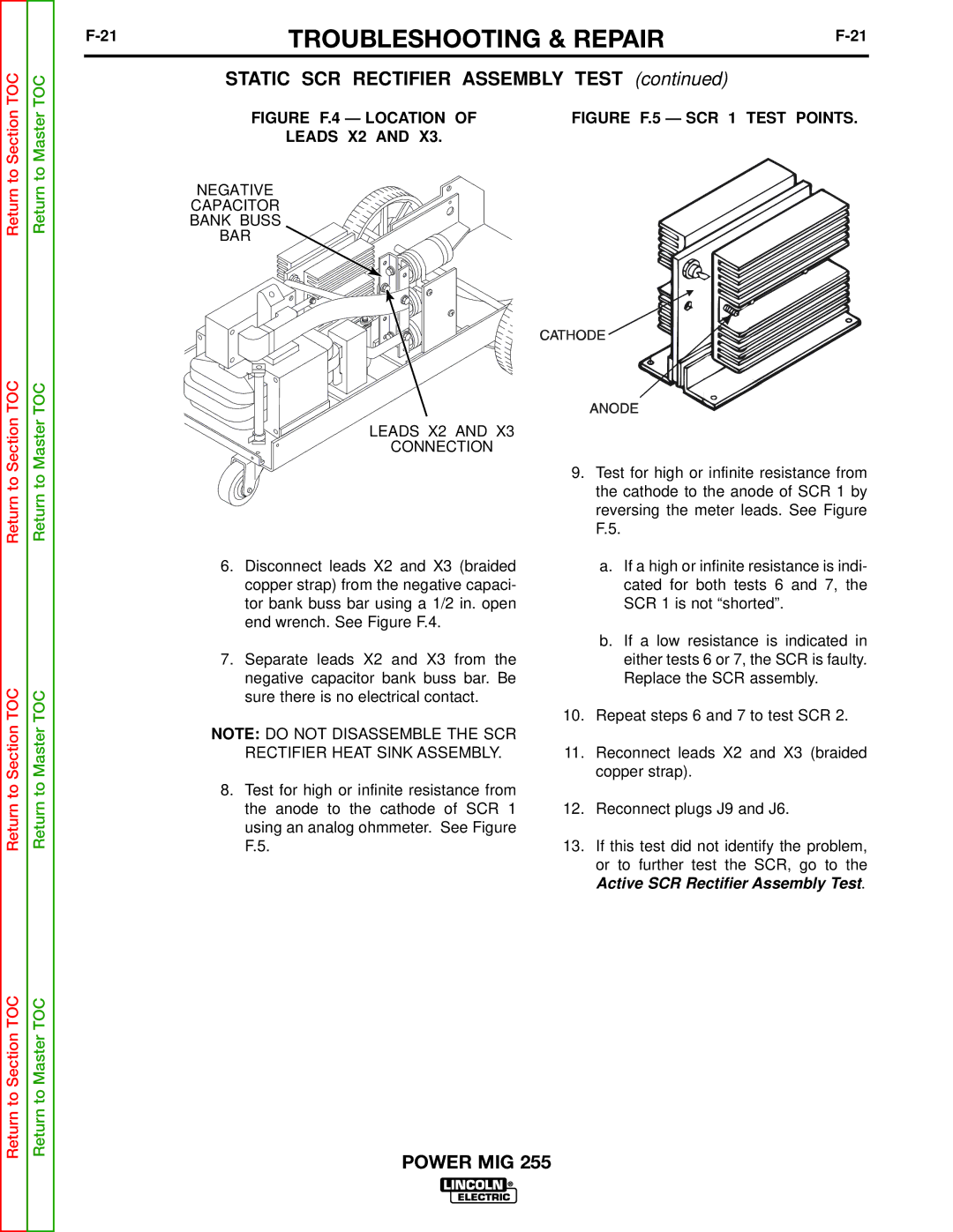
| FIGURE F.4 — LOCATION OF | FIGURE F.5 — SCR 1 TEST POINTS. | |
LEADS X2 AND X3.
NEGATIVE
CAPACITOR
BANK BUSS
BAR
LEADS X2 AND X3
CONNECTION
Return to
Return to Section TOC
Return to
Return to Master TOC
6.Disconnect leads X2 and X3 (braided copper strap) from the negative capaci- tor bank buss bar using a 1/2 in. open end wrench. See Figure F.4.
7.Separate leads X2 and X3 from the negative capacitor bank buss bar. Be sure there is no electrical contact.
NOTE: DO NOT DISASSEMBLE THE SCR RECTIFIER HEAT SINK ASSEMBLY.
8.Test for high or infinite resistance from the anode to the cathode of SCR 1 using an analog ohmmeter. See Figure F.5.
9.Test for high or infinite resistance from the cathode to the anode of SCR 1 by reversing the meter leads. See Figure F.5.
a.If a high or infinite resistance is indi- cated for both tests 6 and 7, the SCR 1 is not “shorted”.
b.If a low resistance is indicated in either tests 6 or 7, the SCR is faulty. Replace the SCR assembly.
10.Repeat steps 6 and 7 to test SCR 2.
11.Reconnect leads X2 and X3 (braided copper strap).
12.Reconnect plugs J9 and J6.
13.If this test did not identify the problem, or to further test the SCR, go to the
Active SCR Rectifier Assembly Test.
Return to Section TOC
Return to Master TOC