THEORY OF OPERATION |
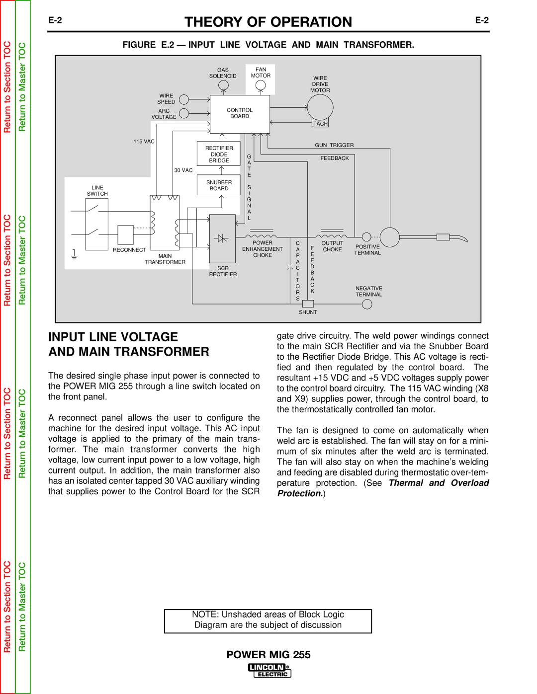
TOC | TOC | FIGURE E.2 — INPUT LINE VOLTAGE AND MAIN TRANSFORMER. | ||||||
|
|
|
|
|
|
| ||
Section | Master |
| GAS | FAN |
|
|
|
|
| SOLENOID | MOTOR |
| WIRE |
| |||
|
|
|
|
| ||||
|
|
|
| DRIVE |
| |||
|
|
|
| MOTOR |
| |||
to | to | WIRE |
|
|
|
|
|
|
SPEED |
|
|
|
|
|
| ||
Return | Return |
|
|
|
|
|
| |
ARC | CONTROL |
|
|
|
| |||
VOLTAGE | BOARD |
|
|
|
| |||
|
|
|
| TACH |
| |||
|
|
|
|
|
|
| ||
|
| 115 VAC |
|
|
|
| GUN TRIGGER |
|
|
|
| RECTIFIER |
|
|
|
| |
|
|
|
|
|
|
|
| |
|
|
| DIODE | G |
|
| FEEDBACK |
|
|
|
| BRIDGE |
|
|
| ||
|
|
| A |
|
|
| ||
|
|
|
|
|
|
| ||
|
|
|
|
|
|
|
| |
|
| 30 VAC |
| T |
|
|
|
|
|
|
|
| E |
|
|
|
|
|
| LINE | SNUBBER | S |
|
|
|
|
|
| BOARD |
|
|
|
| ||
|
| SWITCH |
| I |
|
|
|
|
|
|
|
| G |
|
|
|
|
|
|
|
| N |
|
|
|
|
TOC | TOC |
|
| A |
|
|
|
|
|
| L |
|
|
|
| ||
|
|
|
|
|
|
| ||
Section | Master |
|
| POWER | C | F | OUTPUT | POSITIVE |
RECONNECT |
| ENHANCEMENT | A | CHOKE | ||||
| TERMINAL | |||||||
MAIN |
| CHOKE | P | E |
| |||
|
|
| ||||||
TRANSFORMER | SCR |
| A | E |
|
| ||
to | to |
|
| C | D |
|
| |
| RECTIFIER |
| I | B |
|
| ||
Return | Return |
|
|
| T | A |
|
|
|
|
| O | C |
| NEGATIVE | ||
|
|
| R | K |
| |||
|
|
|
| TERMINAL | ||||
|
|
| S |
|
| |||
|
|
|
|
|
| |||
|
|
|
|
|
|
| ||
|
|
|
|
| SHUNT |
| ||
|
| INPUT LINE VOLTAGE | gate drive circuitry. The weld power windings connect | |
|
| AND MAIN TRANSFORMER | to the main SCR Rectifier and via the Snubber Board | |
|
| to the Rectifier Diode Bridge. This AC voltage is recti- | ||
|
|
| ||
|
| The desired single phase input power is connected to | fied and then regulated by the control board. The | |
|
| resultant +15 VDC and +5 VDC voltages supply power | ||
TOC | TOC | the POWER MIG 255 through a line switch located on | to the control board circuitry. The 115 VAC winding (X8 | |
the front panel. | and X9) supplies power, through the control board, to | |||
|
| |||
Section | Master | A reconnect panel allows the user to configure the | the thermostatically controlled fan motor. | |
| ||||
|
|
| ||
|
| machine for the desired input voltage. This AC input | The fan is designed to come on automatically when | |
to | to | voltage is applied to the primary of the main trans- | weld arc is established. The fan will stay on for a mini- | |
former. The main transformer converts the high | mum of six minutes after the weld arc is terminated. | |||
Return | Return | |||
voltage, low current input power to a low voltage, high | The fan will also stay on when the machine’s welding | |||
|
| current output. In addition, the main transformer also | and feeding are disabled during thermostatic | |
|
| has an isolated center tapped 30 VAC auxiliary winding | perature protection. (See Thermal and Overload | |
|
| that supplies power to the Control Board for the SCR | Protection.) |
Section TOC | Master TOC |
| |
to | to | NOTE: Unshaded areas of Block Logic | |
Diagram are the subject of discussion | |||
Return | Return | ||
| |||
POWER MIG 255 | |||
|
|