SNA400-125, SNR150-100, SNA285-125, SNR200-100, SNA500-125 specifications
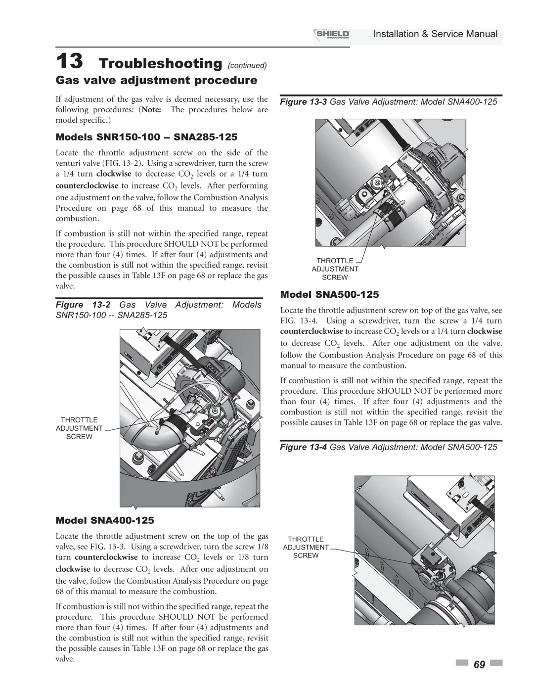
Lochinvar has established itself as a leader in the realm of high-efficiency heating solutions, and its line of condensing boilers, including the SNA500-125, SNR200-100, SNA400-125, SNA285-125, and SNR150-100, exemplifies the brand’s commitment to innovation, efficiency, and reliability.The SNA500-125 model stands out with its impressive heating capacity, designed for larger commercial applications. Featuring advanced modulating burners, it can precisely adjust its output based on real-time demand, significantly enhancing energy efficiency. The stainless steel heat exchanger ensures robust durability and improved thermal performance, while the integrated controls offer advanced diagnostic capabilities and user-friendly operation.
Next in the lineup, the SNR200-100 serves as a versatile option for mid-sized applications. Its compact design allows for flexible installation, making it a valuable choice for facilities with limited space. The boiler incorporates a high-efficiency combustion system that maximizes fuel utilization, while its low NOx emissions technology aligns with environmental standards, reducing the carbon footprint of users.
The SNA400-125 delivers a robust solution for diverse heating needs, equipped with state-of-the-art modulation technology that not only optimizes efficiency but also offers quiet operation – a crucial feature for facilities where noise reduction is paramount. This model also includes built-in redundancy options, enhancing reliability during peak operational periods.
The SNA285-125 provides a balance of performance and efficiency for smaller commercial settings. Its innovative control system offers precise temperature management and easy integration with existing systems. Energy Star certified, this model is not only cost-effective but supports sustainability efforts in various industries.
Lastly, the SNR150-100 is ideally suited for light commercial applications, featuring a compact footprint and excellent heat transfer capabilities. The user-friendly interface and robust safety features make it an excellent choice for operators prioritizing both ease of use and reliability.
All these models incorporate Lochinvar's commitment to superior design and advanced technologies, setting a benchmark in the high-efficiency heating market. With a focus on long-term performance and compliance with modern environmental standards, Lochinvar continues to deliver top-tier solutions tailored to meet diverse customer needs. Whether for large-scale operations or smaller settings, these boilers represent a significant advancement in commercial heating technology.

