Installation & Operation Manual

13 Diagrams (continued)

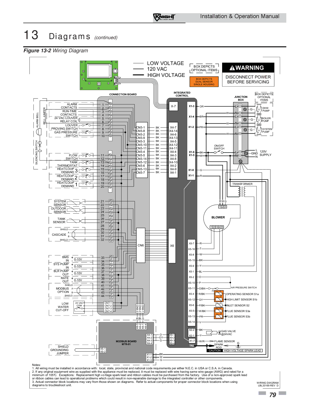
Figure 13-2Wiring Diagram

LOW VOLTAGE 120 VAC HIGH VOLTAGE

BOX DEPICTS

OPTIONAL ITEMS

BOX DEPICTS DUAL SENSOR SINGLE HOUSING


CONNECTION BOARD


INTEGRATED


BOX DEPICTS


CONTROL


JUNCTION


OPTIONAL


BOX


ITEMS


ALARM

1


X-7

X1-3

OR


L


JUMPER

CONTACTS

2


G

DHW

BELL


X1-4

BR


L

RUN-TIME

4


PUMP


3


W

N


CONTACTS


ALARM

BELL

24 VAC LOUVER

5


G

BOILER

LOUVER

7


PUMP


RELAY COIL

6


W

N


PROVING SWITCH

8

CN5-1

BK

X4-7

X1-2

PR


L

G

SYSTEM


CN5-8

BK

X4-14


GAS PRESSURE

9


W

N


PUMP


CN5-2

BK

X4-6


SWITCH

10


CN5-9

BK

X4-13


SWITCH


CN5-3

BK

X4-5


SWITCH


CN5-11

BK

X4-11


CN5-10

BK

X4-12


ON/OFF


SILENCING


TANK

13

CN5-4

BK

X4-4

X1-6

BK


L

L

120V


CN5-12

BK

X4-10

X1-5

W


N

GND

SUPPLY


FLOW

11

CN5-5

BK

X4-3


SWITCH

12

CN5-14

BK

X4-8


N


THERMOSTAT

14

CN5-6

BK

X4-2


HEAT/LOOP

3

15

CN5-13

BK

X4-9

X1-8

G


DEMAND

16

CN5-7

BK

X4-1

X1-1


HEAT/LOOP

2

17


R


DEMAND

18


HEAT/LOOP

1

19


TRANSFORMER


DEMAND

20


SYSTEM


21


R W G


SENSOR


22


1 2 3


OUTDOOR


23


SENSOR


24


25


BLOWER


TANK


26


SENSOR


27


28


1 2 3 4 5


SHIELD


29


A


30


CASCADE B


31


SHIELD


32


R


CN6


X6

X5-7


X5-16

T


BMS


+


33


X5-8

W


0-10V


IN

-

34


X5-15

BK


SYS PUMP


+

0-10V

35


X5-9

Y


IN


-


36


BLR PUMP


+

0-10V

37


X5-1

BL


OUT


-

38


X5-2

O


RATE


+

0-10V

39


OUT

-

40


X5-10

P


SHIELD


41


X5-11


AIR PRESSURE SWITCH


MODBUS


A


42


O/BK


OPTION


B


43


X5-4

R/BK

-T

OPERATING SENSOR S1a


SHIELD


44


-T


X5-12

GY

HIGH LIMIT SENSOR S1b


24 VAC

CN7-1


LOW


CN8-3

CN8-1 CN8-2


X5-6

P/BK

-T

INLET SENSOR S2


CUT-OFF


COM

CN7-2


CN7-4


X5-5

W/BK


FLUE SENSOR S3a


WATER


CN7-3


-T


X5-13

PR

-T

FLUE SENSOR S3b


R BLG


X5-14


X6-3

X6-2 X6-1 X6-4


Y


X2-2

BK

GAS VALVE


X4-1

O

X9-1

X2-1

Y

@24VAC


X4-2

GY

X9-2


MODBUS BOARD

X4-3

G

X9-3

X1-7

W/R

FLAME SENSOR

G


X4-4


X9-4


SHIELD


MTR-01


TR2


SPARK


X5-1


ROD


GROUNDING


CAUTION

HIGH VOLTAGE SPARK LEAD


X5-2


JUMPER


X1-1

BK


X1-2

W


X1-3

G


Notes:

1.All wiring must be installed in accordance with: local, state, provincial and national code requirements per either N.E.C. in USA or C.S.A. in Canada.

2.If any original equipment wire as supplied with the appliance must be replaced, it must be replaced with wire having same wire gauge (AWG) and rated for a minimum of 105°C. Exceptions: Replacement high vo ltage spark lead and ribbon cables must be purchased from the factory. Use of a non-approved spark lead or ribbon cables can lead to operational problems which could result in non-repairable damage to the integrated controller or other components.

3. Actual connector block locations may vary from those shown on diagrams. Refer to actual components for proper connector block locations when using

WIRING DIAGRAM

diagrams to troubleshoot unit.

LBL20169 REV D

79

Page 79
Image 79
Lochinvar WH 55-399 operation manual 2Wiring Diagram

WH 55-399 specifications

The Lochinvar WH 55-399 is a high-efficiency water heater designed for residential and commercial applications, offering a reliable solution for hot water needs. This model represents an advanced approach to water heating, combining cutting-edge technologies and features that ensure optimal performance and energy efficiency.

One of the standout features of the Lochinvar WH 55-399 is its high thermal efficiency, which is a key factor in reducing energy consumption and operating costs. With an efficiency rating exceeding 90%, this water heater ensures that more energy is converted into usable hot water, making it an environmentally friendly choice.

The WH 55-399 utilizes advanced condensing technology, which allows it to extract additional heat from the exhaust gases before they are expelled. This process not only increases efficiency but also significantly decreases greenhouse gas emissions. The unit is also equipped with an intelligent control system that allows for precise temperature adjustments, ensuring that the user has an optimal supply of hot water while maintaining energy savings.

Another important aspect of this model is its impressive recovery rate. The ability to quickly heat water after a significant draw ensures that users will not experience interruptions in their hot water supply, making it ideal for busy households or commercial environments. This is particularly beneficial in applications requiring consistent hot water availability, such as restaurants or athletic facilities.

The Lochinvar WH 55-399 is designed with durability in mind. Constructed from high-quality materials, this water heater boasts a robust tank lined with corrosion-resistant coatings, extending the lifespan of the unit and reducing maintenance needs. Additionally, it features a reliable gas burner and a well-insulated tank, contributing to its overall efficiency and performance.

Safety is also a priority with the WH 55-399. The unit incorporates multiple safety features, including a flame sensor, automatic shut-off valve, and over-temperature protection, ensuring peace of mind for users.

In summary, the Lochinvar WH 55-399 stands out with its combination of high efficiency, advanced technology, and durable construction. Whether for residential or commercial use, this water heater provides a dependable and cost-effective solution for all hot water needs. Its innovative design and performance characteristics make it a top choice for anyone seeking a premium water heating option.