Index IN

Numerics

559C Outdoor CAUs, fastening antenna for, 3-42559D DCAUs

fastening antenna for,

3-33


installing brand new,

3-34


replacing


ceiling-mounted CAUs with, 3-34

wall-mounted CAUs with, 3-35

9601 Wireless Terminal


description, 3-50


entering access codes via,

3-54

obtaining IPEI via,

3-54


power, 3-22


updating firmware for,

4-2


9630 Series Wireless Terminal


description, 3-52


entering access codes via,

3-54

environment, 3-5


obtaining IPEI via,

3-54


storage temperatures,

3-5


updating firmware for,

4-2


A

administering


carrier frequencies,

2-7

frequencies, 2-6


port networks containing RCs, 2-7

Radio Controllers,

2-5

American Wire Gauge,

3-22

antenna, fastening for

559C Outdoor CAU, 3-42

559D Dipole CAU, 3-33

B

batteries contents, 3-2handling, 3-2precautions, 3-2

recycling and disposing, 3-2

C

cabling, power and interface,

3-22


carrier frequencies, administering,

2-7


CAU brackets, mounting,

3-44


Cell Antenna Units


cable requirements,

3-3


coaxial connections to WFBs,

3-22


connection to WFBs,

3-30


description, 3-30


distance


between, 3-30


from WFBs,

3-30


installing


559B Outdoor,

3-36


559D DCAU,


3-32


indoor, 3-30


maintaining openings for,

3-3


power, 3-22


powering, 3-30


vis-a-vis return air plenum,

3-31


commands


add radio-controller,

2-5,2-10,5-2


add station,

2-14,5-3


change alias station,

5-2


change carrier-frequencies,2-7,5-2


change circuit-packs,

2-8,5-2


change radio-controller,

5-2


change station,

5-3


change system-parameters customer-options,

2-1,5-3

change system-parameters features,

5-3


change system-parameters wireless,

2-3,5-3


disable WT-stations,

5-3


display alias station,

5-2


display carrier-frequencies,

5-2


display circuit packs,

5-2


display station,

5-3


display system-parameters customer-options,

5-3

display system-parameters features,

5-3


display system-parameters wireless,

5-3


enable WT-stations,

5-3


list bridged-extension,

5-2


list configuration all,

2-9,5-2


list configuration board,

5-2


list configuration firmware-versions,

5-2


list configuration radio-controller,5-2


list configuration WT-stations,

5-3


remove radio-controller,

5-2


remove station,

5-3


status card-mem,

5-2


status radio-controller,

5-2


test radio-sync,

5-3


test WFB,

5-3


upgrade firmware,

5-2


wireless business system administration, 5-2


Issue 5 June 1999 IN-1

Page 129
Image 129
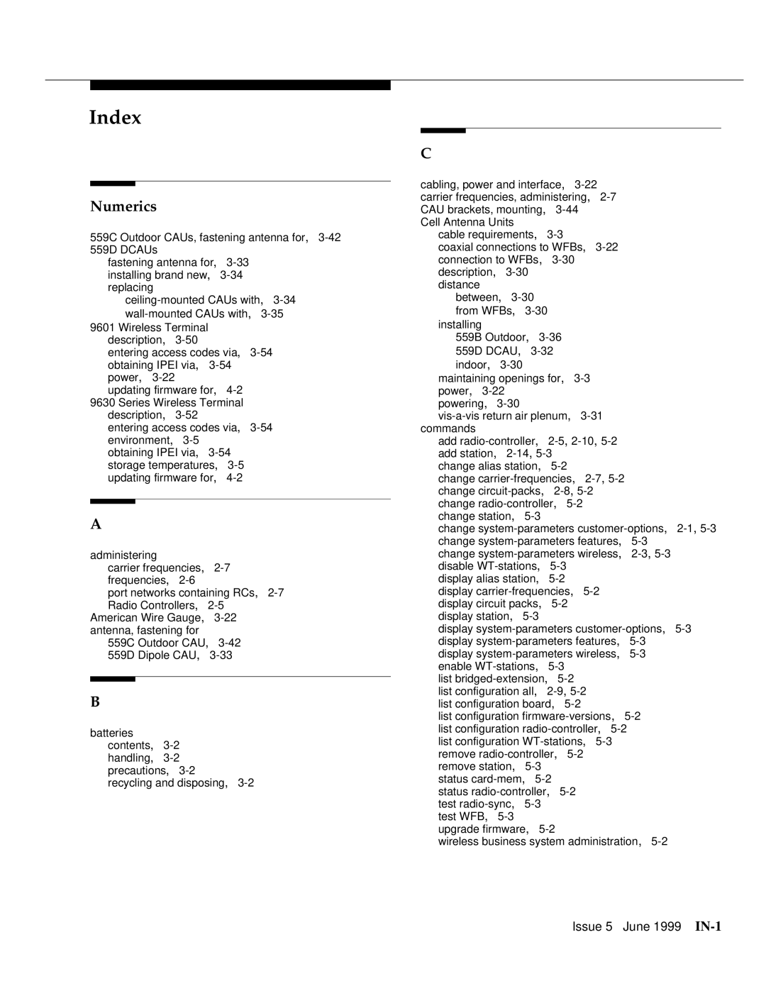
Lucent Technologies 555-232-102 manual Index, Numerics

555-232-102 specifications

Lucent Technologies, a key player in the telecommunications industry during the late 20th century, played a significant role in advancing the technology that shaped modern communication systems. Among its diverse product offerings, the 555-232-102 model stands out as an exemplary piece of equipment, notable for its robustness and versatility.

The 555-232-102 is primarily a telecommunications switch designed for both small and large-scale networks, making it suitable for a variety of applications. Its main features include a highly reliable architecture that supports both voice and data transmission seamlessly. This model incorporates advanced signaling technologies, which enable it to handle multiple connections simultaneously, enhancing its efficiency in busy environments.

One of the defining characteristics of the 555-232-102 is its modular design. This allows for easy upgrades and customization depending on the user’s specific needs. With various interfaces available, including analog and digital connections, the device caters to a wide range of telecommunications technologies, from traditional landline systems to modern VoIP setups.

The technology embedded in the 555-232-102 also emphasizes security and redundancy. Built-in failover protocols ensure that even in the event of a hardware failure, communication remains uninterrupted. This aspect is crucial for critical infrastructure where downtime can have serious consequences.

Moreover, the 555-232-102 supports multiple protocols, making it future-proof as telecommunications standards evolve. This adaptability allows organizations to invest in a solution that remains relevant for years to come without the need for complete overhauls.

Another key technological feature is its user-friendly management interface. This interface allows network administrators to monitor performance metrics, troubleshoot issues, and configure settings with ease. The intuitive design reduces the learning curve and enables rapid deployment in various environments.

Energy efficiency is another characteristic of the 555-232-102 that aligns with modern standards of sustainability. By optimizing power consumption without compromising performance, Lucent Technologies demonstrates a commitment to eco-friendly practices.

In conclusion, the Lucent Technologies 555-232-102 embodies the intersection of reliability, versatility, and advanced telecommunications technology. Its modular design, support for multiple protocols, robust security features, and user-friendly management tools make it a significant asset for any organization looking to enhance its communication infrastructure. As modern telecommunications continue to evolve, the legacy of the 555-232-102 serves as a benchmark for future innovations.