Hardware Installation

To

RXT 1

RXT 2

RC/Cross-


Connect

TXT 3

(see

TXR 6

Note 5)


Primary

Primary


1151A1 or


146E


Protection

Protection

146E


1151A2

1

RXT 1


8

RXT


RXT


RXT 8


1 RXT 1

Line


2

RXT 2

Equipment

7

RXR


RXR


RXR 7


2 RXR 2


Line

Phone

7 -48 7


Protector 1


(see Note 3)


(see Note 3)


(see Note 2)


Protector 1


8

GND 8 WFB

6

TXT


TXT


TXT 6

(see Note 2)

3 TXT 3


3

TXT 3


3

TXR


TXR


TXR 3


6 TXR 6


6

TXR 6


(see Note 1)


(see Note 1)


(see Note 1)


(see Note 1)


Out-of-

Building Span

(see Notes 4 and 8)

117VAC

NOTES:

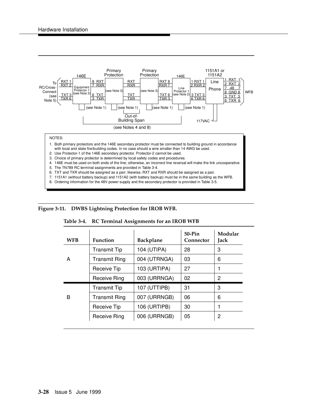
1.Both primary protectors and the 146E secondary protector must be connected to building ground in accordance with local and state fire/building codes. In no case should a wire smaller than 14 AWG be used.

2.Use Protector-1 of the 146E secondary protector. Protector-2 cannot be used.

3.Choice of primary protector is determined by local safety codes and procedures.

4.146E must be used on both ends of the line; otherwise, an incorrect line reversal will make the link uncooperative.

5.The TN789 RC terminal assignments are provided in Table 3-4.

6.TXT and TXR should be assigned as a pair; likewise, RXT and RXR should be assigned as a pair.

7.1151A1 (without battery backup) and 1151A2 (with battery backup) must be in the same building as the WFB.

8.Ordering information for the 48V power supply and the secondary protector is provided in Table 3-5.

Figure 3-11. DWBS Lightning Protection for IROB WFB.


Table 3-4.

RC Terminal Assignments for an IROB WFB


50-Pin


Modular


WFB

Function

Backplane

Connector


Jack


Transmit Tip

104

(UTIPA)

28


3


A

Transmit Ring

004

(UTRNGA)

03


6


Receive Tip

103

(URTIPA)

27


1


Receive Ring

003

(URRNGA)

02


2


Transmit Tip

107

(UTTIPB)

31


3


B

Transmit Ring

007

(URRNGB)

06


6


Receive Tip

106

(URTIPB)

30


1


Receive Ring

006

(URRNGB)

05


2


3-28Issue 5 June 1999

Page 68
Image 68
Lucent Technologies 555-232-102 manual Wfb

555-232-102 specifications

Lucent Technologies, a key player in the telecommunications industry during the late 20th century, played a significant role in advancing the technology that shaped modern communication systems. Among its diverse product offerings, the 555-232-102 model stands out as an exemplary piece of equipment, notable for its robustness and versatility.

The 555-232-102 is primarily a telecommunications switch designed for both small and large-scale networks, making it suitable for a variety of applications. Its main features include a highly reliable architecture that supports both voice and data transmission seamlessly. This model incorporates advanced signaling technologies, which enable it to handle multiple connections simultaneously, enhancing its efficiency in busy environments.

One of the defining characteristics of the 555-232-102 is its modular design. This allows for easy upgrades and customization depending on the user’s specific needs. With various interfaces available, including analog and digital connections, the device caters to a wide range of telecommunications technologies, from traditional landline systems to modern VoIP setups.

The technology embedded in the 555-232-102 also emphasizes security and redundancy. Built-in failover protocols ensure that even in the event of a hardware failure, communication remains uninterrupted. This aspect is crucial for critical infrastructure where downtime can have serious consequences.

Moreover, the 555-232-102 supports multiple protocols, making it future-proof as telecommunications standards evolve. This adaptability allows organizations to invest in a solution that remains relevant for years to come without the need for complete overhauls.

Another key technological feature is its user-friendly management interface. This interface allows network administrators to monitor performance metrics, troubleshoot issues, and configure settings with ease. The intuitive design reduces the learning curve and enables rapid deployment in various environments.

Energy efficiency is another characteristic of the 555-232-102 that aligns with modern standards of sustainability. By optimizing power consumption without compromising performance, Lucent Technologies demonstrates a commitment to eco-friendly practices.

In conclusion, the Lucent Technologies 555-232-102 embodies the intersection of reliability, versatility, and advanced telecommunications technology. Its modular design, support for multiple protocols, robust security features, and user-friendly management tools make it a significant asset for any organization looking to enhance its communication infrastructure. As modern telecommunications continue to evolve, the legacy of the 555-232-102 serves as a benchmark for future innovations.