Manuals
/
Matsushita
/
Computer Equipment
/
Laptop
Matsushita
CF-08TX1A1M
manual
Wlan 1 SYCHIPWLAN/ BT Board
Models:
CF-08TX1A1M
1
86
87
87
Download
87 pages
52.91 Kb
80
81
82
83
84
85
86
87
Troubleshooting
Specifications
Parts list
Flow Chart
Bluetooth
Turn on the wireless display
Disassembly/Reassembly
Battery pack Headphone jack
When deleting settings
How to
Page 86
Image 86
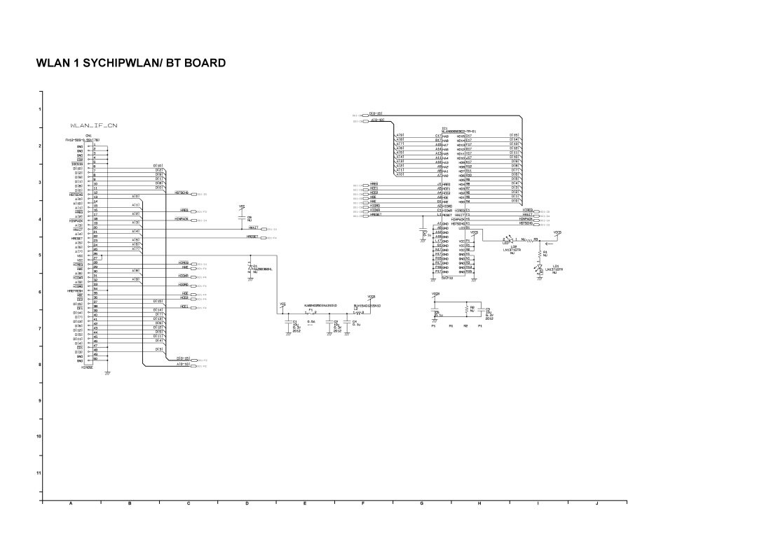
WLAN 1 SYCHIPWLAN/ BT BOARD
1
2
3
4
5
6
7
8
9
10
11
A
B
C
D
E
F
G
H
I
J
Page 85
Page 87
Page 86
Image 86
Page 85
Page 87
Contents
CF-08TX1A1M
Page
Page
Avoid Extreme Heat, Cold and Direct Sun- light
Precautions
Avoid Heat
Do Not Put into a Micro- wave
Stop Using
Contents
Specifications
Main Specifications
Wireless LAN
Bluetooth
Disclaimer Trademarks
Introduction
Copyright
Description of parts
Battery pack Headphone jack
Stylus holder Security lock Speaker Expansion bus connector
Microphone jack
Using the Tether
Attaching the Tether
Connect to the server
Turn on the wireless display
Starting up/Shutting Down
When settings have been changed
Make the settings only for the Supervisor
When terminating the connection
When deleting settings
Shutting Down power off the wireless display
Flow Chart
Diagnosis & Repair
Troubleshooting
Sdram march test
Self Test Program
CPU Type check
Chip ID check for LAN9118
Test register check for the source microcomputer
ID check for 2700G
How to Restart
Display
Troubleshooting
Starting Up
Touchscreen
Shut Down
Wireless Communication
Connecting Peripherals
Sound
Block Diagram
DC/DC VCC5P0V LCD FET
Wiring Connection Diagram
Dock CON PCB
Preparation
Disassembly/Reassembly
Removing the Battery Pack
Removing the Display Unit
Removing IO Power PCB
Removing the Main PCB
Removing the USB PCB
Removing the Wlan PCB Removing the Speaker
Removing the Audio Con PCB
Removing the Dock Con PCB
Removing the Bluetooth Wlan R PCB
Removing the Wlan L PCB
Removing the SW LED PCB
Removing the LCD Unit and the Inverter
Reassembly Instructions
Setting the LCD Unit and the Inverter
Preparations for backlight
Safety Working
LCD PWB Sheet
Preparations for Touchscreen
Setting the SW LED PCB
Assembly of the LCD Block
Assembly of the SW LED PCB
Setting the Dock Con PCB
Assembly of the Dock CON PCB
Setting the Bluetooth Wlan R PCB
Setting the Wlan L PCB
Setting the Audio Con PCB
Setting the USB PCB
Setting the Speaker
Setting the Wlan PCB
Setting the IO Power PCB
Setting the Main PCB
USB PCB
FFC
Setting the Display Unit
Assembly of the Display unit
Cable Hold Sheet
Setting the Battery Pack
Battery Pack
Slide the knob to the outside and lock firmly
Exploded View
10-1
10-2
10-3
Replacement Parts List
11-1
11-2
11-3
11-4
REF. no and Area
11-5
11-6
11-7
11-8
11-9
11-10
11-11
11-12
11-13
11-14
11-15
Resistor Array
11-16
11-17
11-18
11-19
11-20
ERJ3GEYJ562V
11-21
11-22
11-23
CF-08 Printed Circuit Board
Main PCB
SW LED PCB
CF-08 Schematic Diagram IO Power 1 I/F Connector
RJ45LAN
IO Power 2 DCIN/ Battery
For Cradle DC-IN
IO Power 3 Charger
LTC4008EGN#TRPBF
IO Power 4 VA3,VA5
SENSE2
IO Power 5 EC
ECFlash
IO Power 6 Overprotect
Wlan 1 SYCHIPWLAN/ BT Board
Wlan 2 SYCHIPWLAN/ BT Board
Top
Page
Image
Contents