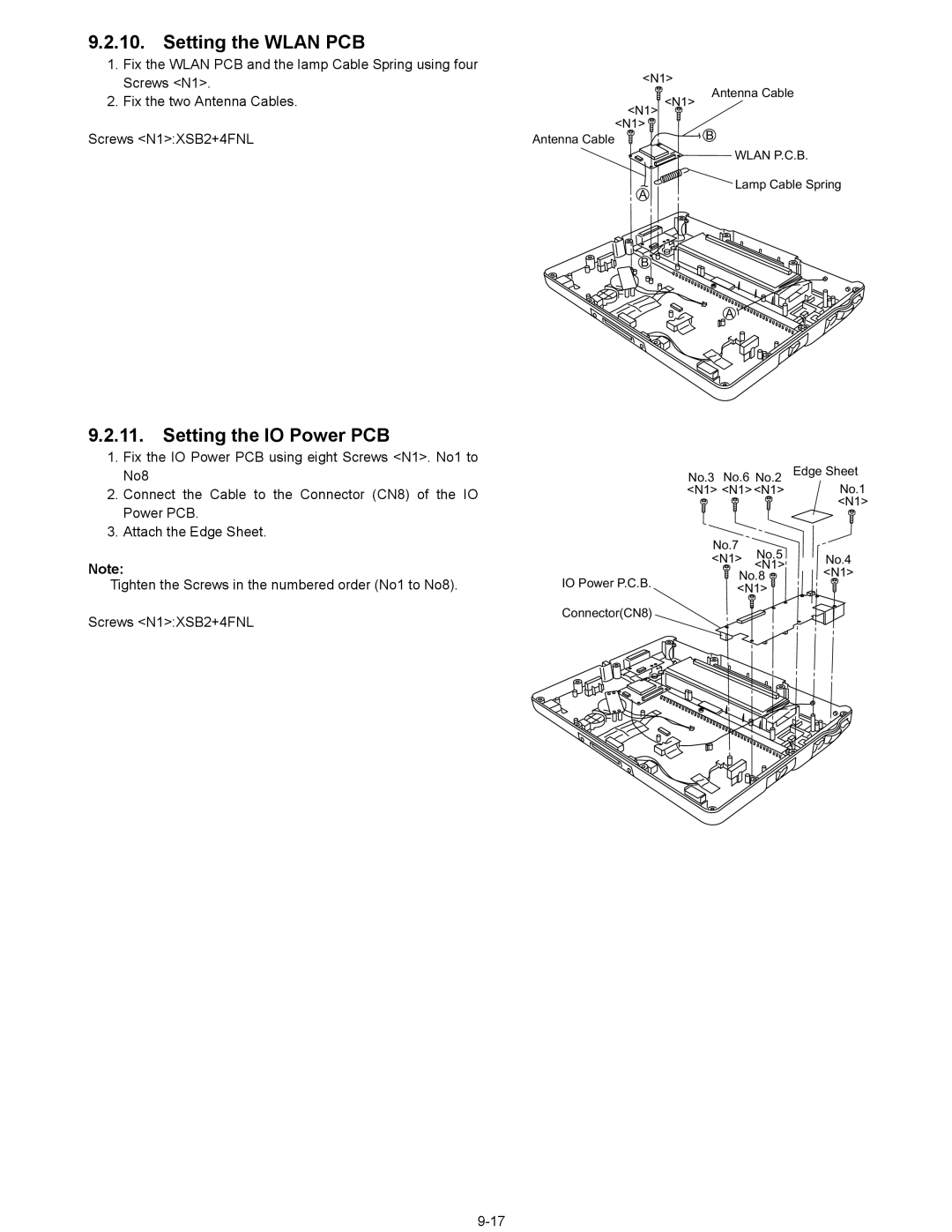
9.2.10. Setting the WLAN PCB
1.Fix the WLAN PCB and the lamp Cable Spring using four Screws <N1>.
2.Fix the two Antenna Cables.
Screws <N1>:XSB2+4FNL
9.2.11.Setting the IO Power PCB
1.Fix the IO Power PCB using eight Screws <N1>. No1 to No8
2.Connect the Cable to the Connector (CN8) of the IO Power PCB.
3.Attach the Edge Sheet.
Note:
Tighten the Screws in the numbered order (No1 to No8).
Screws <N1>:XSB2+4FNL
<N1>
| Antenna Cable |
| <N1> <N1> |
| <N1> |
Antenna Cable | B |
| |
| WLAN P.C.B. |
| Lamp Cable Spring |
| A |
| B |
| A |
No.3 | No.6 No.2 | Edge Sheet | ||
<N1> | <N1> <N1> | No.1 | ||
|
|
| <N1> | |
No.7 | No.5 |
| ||
<N1> | No.4 | |||
<N1> | ||||
IO Power P.C.B. | No.8 | <N1> | ||
<N1> |
| |||
|
| |||
Connector(CN8) |
|
|
| |