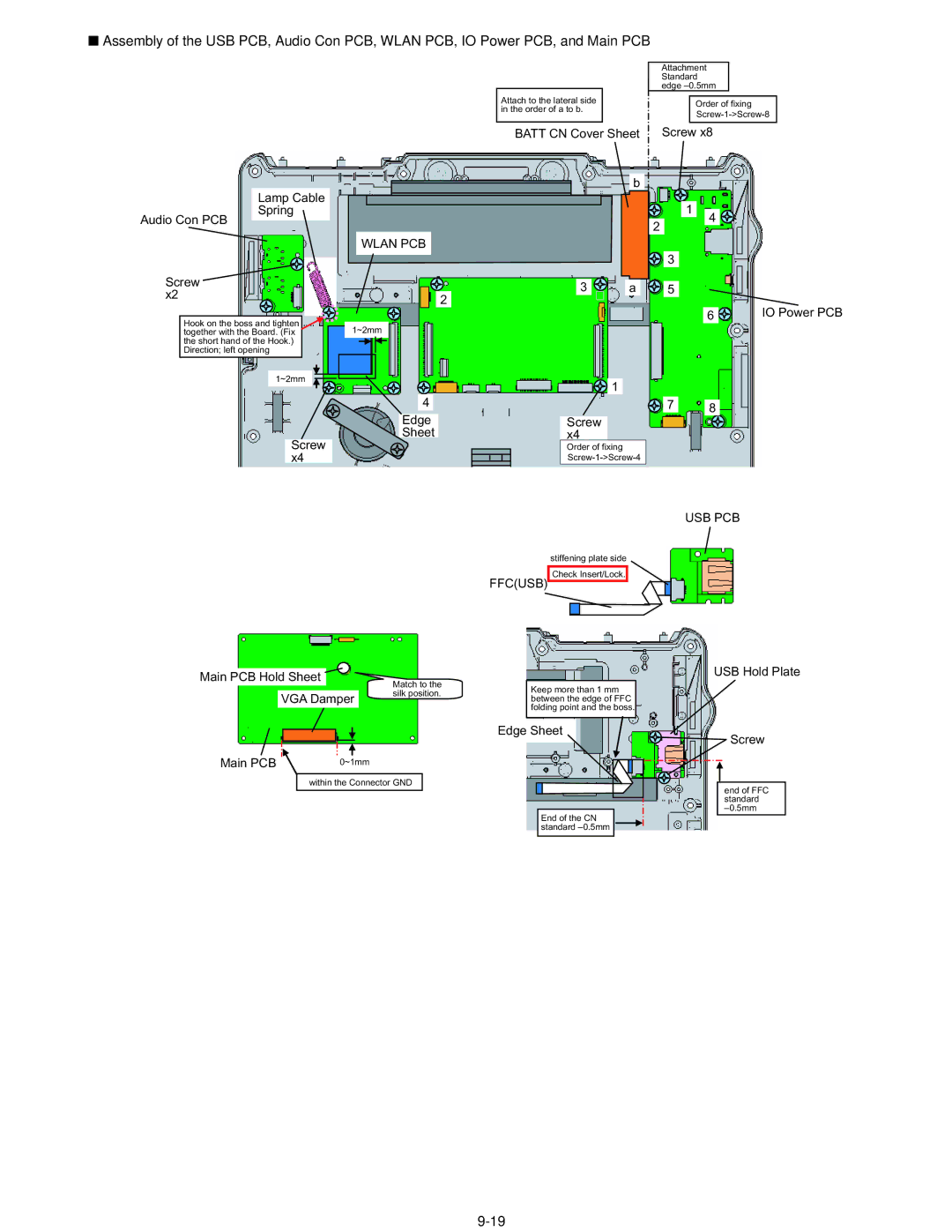
■Assembly of the USB PCB, Audio Con PCB, WLAN PCB, IO Power PCB, and Main PCB
Attach to the lateral side in the order of a to b.
Attachment
Standard edge
Order of fixing
BATT CN Cover Sheet ![]() Screw x8
Screw x8
Lamp Cable
Spring
Audio Con PCB
Screw x2
b
![]() 1 2
1 2
WLAN PCB
![]() 3
3
3 | a | 5 |
2
4
Hook on the boss and tighten together with the Board. (Fix the short hand of the Hook.)
Direction; left opening
1~2mm
Screw x4
6 | IO Power PCB |
1~2mm
| 1 |
|
4 | 7 | 8 |
Edge | Screw |
|
Sheet | x4 |
|
| Order of fixing |
|
|
| |
|
| USB PCB |
| stiffening plate side |
|
| Check Insert/Lock. |
|
| FFC(USB) |
|
Main PCB Hold Sheet
VGA Damper
Match to the silk position.
Keep more than 1 mm between the edge of FFC folding point and the boss.
Edge Sheet
USB Hold Plate
Screw
Main PCB | 0~1mm |
within the Connector GND
End of the CN standard
end of FFC standard