Dual, 65Msps, 12-Bit, IF/Baseband ADC
|
|
|
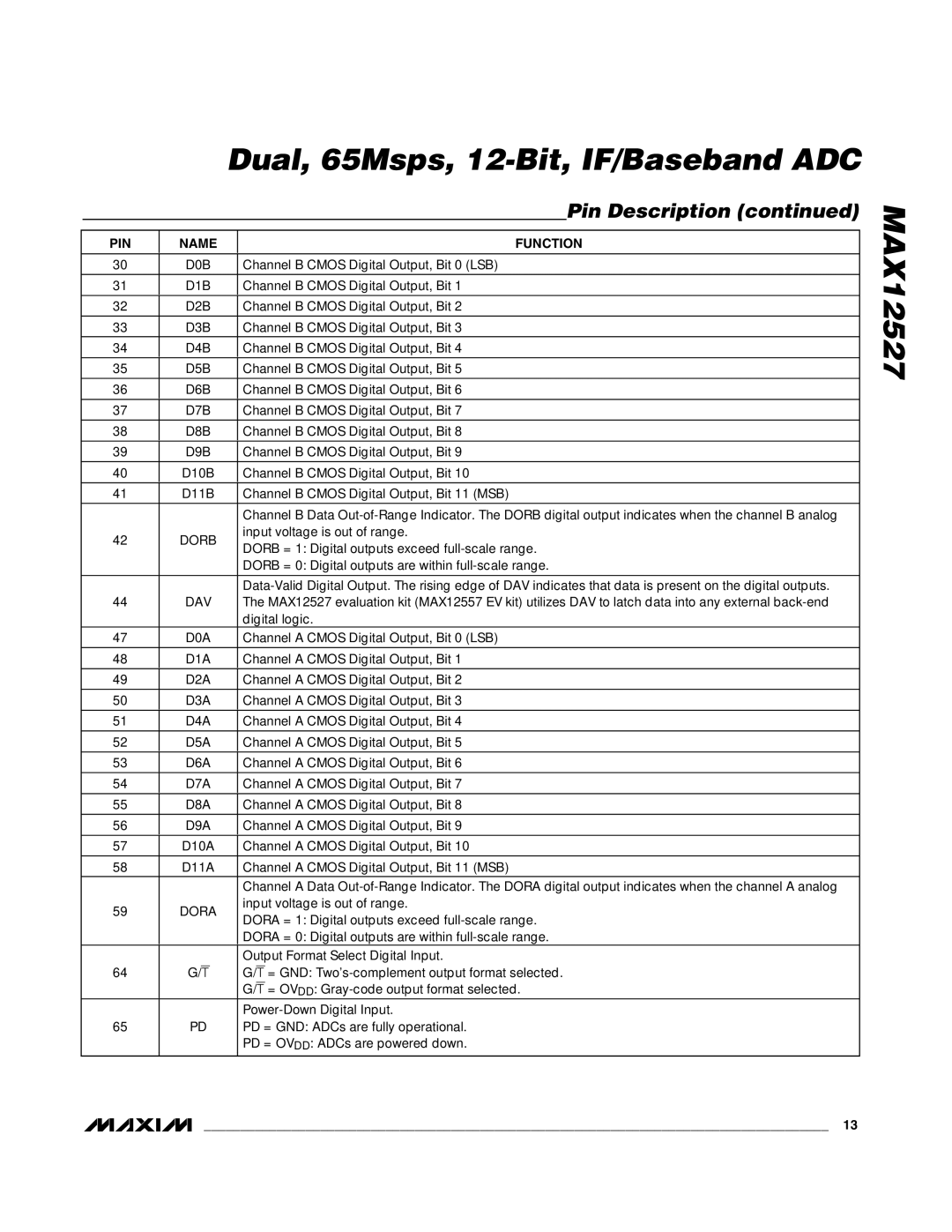
| Pin Description (continued) | |
|
|
|
|
| |
PIN | NAME |
| FUNCTION | ||
|
|
|
|
| |
30 | D0B | Channel B CMOS Digital Output, Bit 0 (LSB) | |||
|
|
|
|
| |
31 | D1B | Channel B CMOS Digital Output, Bit 1 | |||
|
|
|
|
| |
32 | D2B | Channel B CMOS Digital Output, Bit 2 | |||
|
|
|
|
| |
33 | D3B | Channel B CMOS Digital Output, Bit 3 | |||
34 | D4B | Channel B CMOS Digital Output, Bit 4 | |||
|
|
|
|
| |
35 | D5B | Channel B CMOS Digital Output, Bit 5 | |||
|
|
|
|
| |
36 | D6B | Channel B CMOS Digital Output, Bit 6 | |||
|
|
|
|
| |
37 | D7B | Channel B CMOS Digital Output, Bit 7 | |||
|
|
|
|
| |
38 | D8B | Channel B CMOS Digital Output, Bit 8 | |||
39 | D9B | Channel B CMOS Digital Output, Bit 9 | |||
|
|
|
|
| |
40 | D10B | Channel B CMOS Digital Output, Bit 10 | |||
|
|
|
|
| |
41 | D11B | Channel B CMOS Digital Output, Bit 11 (MSB) | |||
|
|
|
|
| |
|
| Channel B Data | |||
42 | DORB | input voltage is out of range. | |||
DORB = 1: Digital outputs exceed | |||||
|
| ||||
|
| DORB = 0: Digital outputs are within | |||
|
|
|
|
| |
|
| ||||
44 | DAV | The MAX12527 evaluation kit (MAX12557 EV kit) utilizes DAV to latch data into any external | |||
|
| digital logic. | |||
47 | D0A | Channel A CMOS Digital Output, Bit 0 (LSB) | |||
|
|
|
|
| |
48 | D1A | Channel A CMOS Digital Output, Bit 1 | |||
49 | D2A | Channel A CMOS Digital Output, Bit 2 | |||
|
|
|
|
| |
50 | D3A | Channel A CMOS Digital Output, Bit 3 | |||
51 | D4A | Channel A CMOS Digital Output, Bit 4 | |||
|
|
|
|
| |
52 | D5A | Channel A CMOS Digital Output, Bit 5 | |||
|
|
|
|
| |
53 | D6A | Channel A CMOS Digital Output, Bit 6 | |||
|
|
|
|
| |
54 | D7A | Channel A CMOS Digital Output, Bit 7 | |||
|
|
|
|
| |
55 | D8A | Channel A CMOS Digital Output, Bit 8 | |||
|
|
|
|
| |
56 | D9A | Channel A CMOS Digital Output, Bit 9 | |||
57 | D10A | Channel A CMOS Digital Output, Bit 10 | |||
|
|
|
|
| |
58 | D11A | Channel A CMOS Digital Output, Bit 11 (MSB) | |||
|
|
|
|
| |
|
| Channel A Data | |||
59 | DORA | input voltage is out of range. | |||
DORA = 1: Digital outputs exceed | |||||
|
| ||||
|
| DORA = 0: Digital outputs are within | |||
|
| Output Format Select Digital Input. | |||
64 | G/T | G/T = GND: | |||
|
| G/T = OVDD: | |||
|
| ||||
65 | PD | PD = GND: ADCs are fully operational. | |||
|
| PD = OVDD: ADCs are powered down. | |||
MAX12527
______________________________________________________________________________________ 13