Dual, 65Msps, 12-Bit, IF/Baseband ADC
MAX12527
Applications Information
Using Transformer Coupling
In general, the MAX12527 provides better SFDR and THD with fully differential input signals than single- ended input drive, especially for input frequencies above 125MHz. In differential input mode,
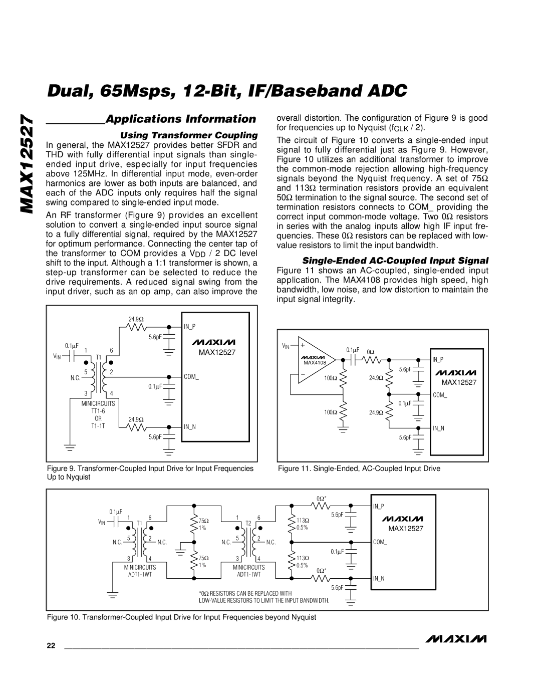
An RF transformer (Figure 9) provides an excellent solution to convert a
|
|
| 24.9Ω |
|
|
| IN_P |
|
|
| 5.6pF |
| 0.1µF |
| MAX12527 |
VIN | 1 | 6 | |
T1 |
|
| |
| 5 | 2 | COM_ |
| N.C. |
| |
| 3 | 4 | 0.1µF |
|
| ||
| MINICIRCUITS |
| |
|
|
| |
| OR |
| 24.9Ω |
|
| IN_N | |
|
|
| 5.6pF |
overall distortion. The configuration of Figure 9 is good for frequencies up to Nyquist (fCLK / 2).
The circuit of Figure 10 converts a
Single-Ended AC-Coupled Input Signal
Figure 11 shows an AC-coupled, single-ended input application. The MAX4108 provides high speed, high bandwidth, low noise, and low distortion to maintain the input signal integrity.
VIN | 0.1µF | 0Ω |
| ||
|
| |
MAX4108 |
| IN_P |
| 5.6pF | |
|
| |
100Ω |
| 24.9Ω |
|
| MAX12527 |
|
| COM_ |
|
| 0.1µF |
100Ω |
| 24.9Ω |
|
| IN_N |
|
| 5.6pF |
Figure 9. | Figure 11. |
Up to Nyquist |
|
|
|
|
|
|
|
| 0Ω* |
| 0.1µF |
|
|
|
|
| 5.6pF |
| 1 | 6 |
| 1 | 6 |
| |
VIN | 75Ω |
| 113Ω | ||||
T1 |
| T2 |
|
| |||
|
|
| 1% |
|
|
| 0.5% |
| 5 | 2 | N.C. | 5 | 2 | N.C. |
|
| N.C. |
| N.C. |
|
| ||
|
|
| 75Ω |
|
|
| 0.1µF |
| 3 | 4 | 3 | 4 |
| 113Ω | |
| MINICIRCUITS | 1% | MINICIRCUITS |
| 0.5% | ||
|
|
| 0Ω* | ||||
|
|
| |||||
|
|
|
| ||||
|
|
| *0Ω RESISTORS CAN BE REPLACED WITH | 5.6pF | |||
|
|
|
| ||||
IN_P
MAX12527
COM_
IN_N
Figure 10. Transformer-Coupled Input Drive for Input Frequencies beyond Nyquist
22 ______________________________________________________________________________________