Installation and User Manual
2.7System Connections
WARNING | This type of connections must be carried out by qualified electrical personnel. |
| Before carrying out any connections, check that battery circuit breaker 14 is |
| OFF and that the upstream protection devices (Normal and Bypass AC |
| sources) are open (OFF/OPEN). |
|
|
2.7.1Connections with Common Normal and Bypass AC Sources (Single Mains)
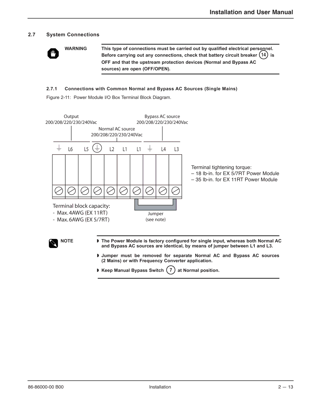
Figure 2-11: Power Module I/O Box Terminal Block Diagram.
Output | Bypass AC source |
200/208/220/230/240Vac | 200/208/220/230/240Vac |
Normal AC source
200/208/220/230/240Vac
L6 L5
L2 L1 L1
L4 L3
Terminal tightening torque:
– 18
– 35
Terminal block capacity: |
|
|
|
|
|
| ||
|
|
|
|
|
| |||
- Max. 4AWG (EX 11RT) |
|
|
|
| ||||
|
| Jumper | ||||||
- Max. 6AWG (EX 5/7RT) |
|
| (see note) | |||||
|
|
|
|
|
|
|
|
|
| NOTE | ◗ The | Power Module is factory configured for single input, whereas both Normal AC | |||||
| ||||||||
|
| and | Bypass AC sources are identical, by means of jumper between L1 and L3. | |||||
|
|
|
|
|
|
|
|
|
◗Jumper must be removed for separate Normal AC and Bypass AC sources (2 Mains) or with Frequency Converter application.
◗ Keep Manual Bypass Switch 7 at Normal position.
Installation | 2 — 13 |