EX 5/7/11RT Systems
4.3Re-connecting the Power Module
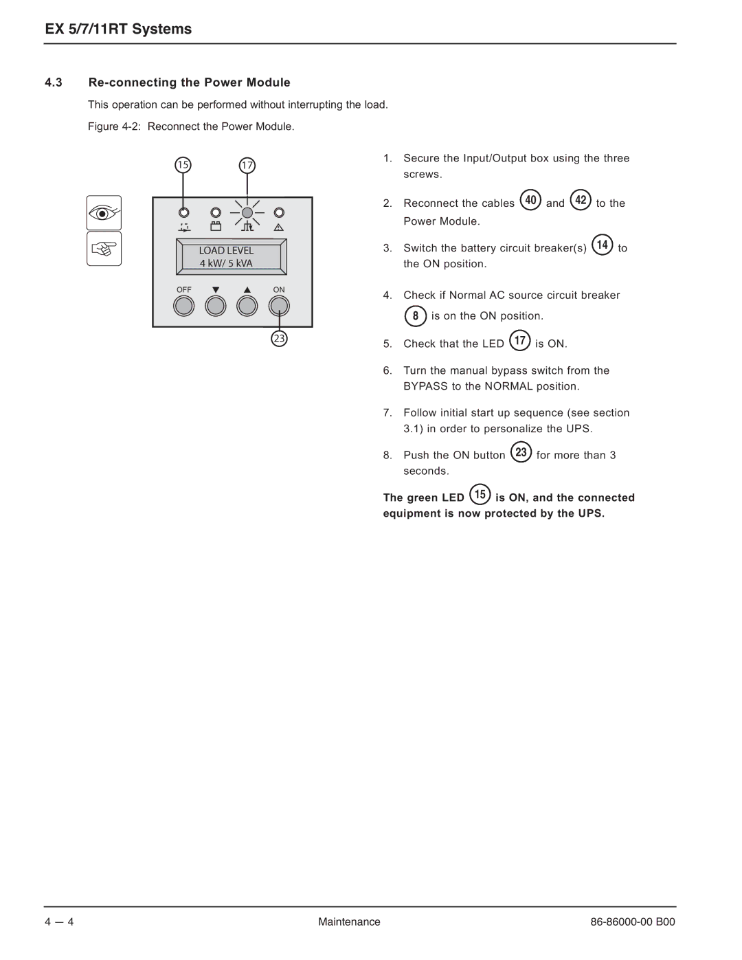
This operation can be performed without interrupting the load. Figure
15 17
LOAD LEVEL 4 kW/ 5 kVA
OFFON
23
1.Secure the Input/Output box using the three screws.
2.Reconnect the cables 40 and 42 to the Power Module.
3.Switch the battery circuit breaker(s) 14 to the ON position.
4.Check if Normal AC source circuit breaker
8 is on the ON position.
5.Check that the LED 17 is ON.
6.Turn the manual bypass switch from the BYPASS to the NORMAL position.
7.Follow initial start up sequence (see section 3.1) in order to personalize the UPS.
8.Push the ON button 23 for more than 3 seconds.
The green LED 15 is ON, and the connected
equipment is now protected by the UPS.
4 — 4 | Maintenance |