EX 5/7/11RT Systems
Proceed as follows:
1.For normal AC input, make connections to L1, L2 and ![]() terminals only. No connections are required for Bypass AC input. Make connections to
terminals only. No connections are required for Bypass AC input. Make connections to ![]() , L5, L6 terminals for output.
, L5, L6 terminals for output.
CAUTION: | Always connect the earth ground wire first. |
| Jumper must be between L1 and L3. System is factory configured for 208VAC |
| output. |
|
|
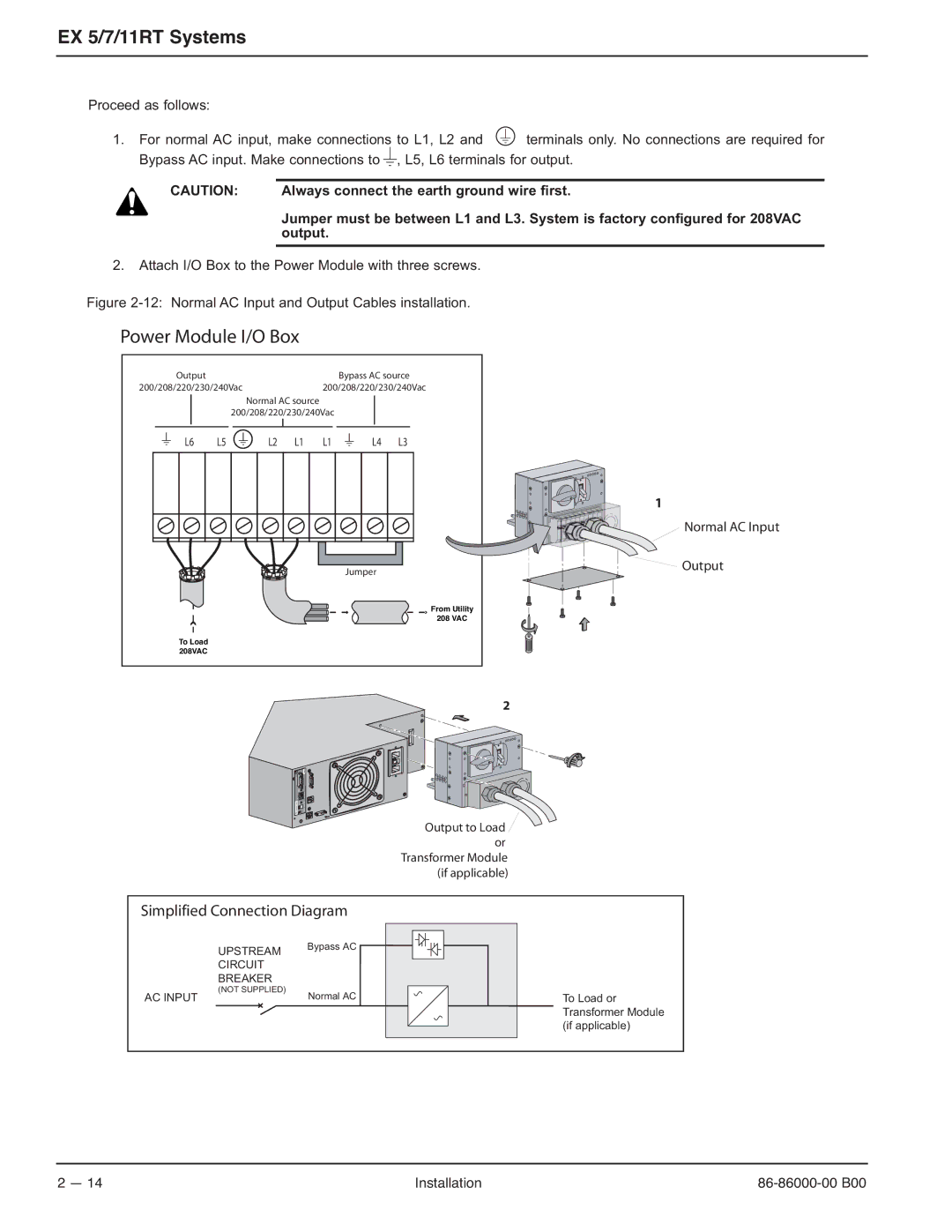
2.Attach I/O Box to the Power Module with three screws.
Figure 2-12: Normal AC Input and Output Cables installation.
Power Module I/O Box
Output | Bypass AC source |
200/208/220/230/240Vac | 200/208/220/230/240Vac |
Normal AC source
200/208/220/230/240Vac
L6 L5
L2 L1 L1
L4 L3
OFF
O
1
Normal AC Input
Jumper | Output |
|
From Utility
208 VAC
To Load 208VAC
2
66074
OFF O
Output to Load ![]() or
or
Transformer Module (if applicable)
Simplified Connection Diagram
UPSTREAM | Bypass AC |
| |
CIRCUIT |
|
BREAKER |
|
(NOT SUPPLIED) |
|
AC INPUT | Normal AC | To Load or |
|
| Transformer Module |
|
| (if applicable) |
2 — 14 | Installation |