Manuals
/
Middleby Marshall
/
Kitchen Appliance
/
Oven
Middleby Marshall
PS314SBI English, Iv. Thermocouple Installation, V. Conveyor Installation
Models:
PS314SBI
1
8
60
60
Download
60 pages
3.05 Kb
5
6
7
8
9
10
11
12
Specifications
Install
Maintenance
Symptomproblem
Iii. Assembly
Dailystartupprocedure
HourService Hotline
Solution
Page 8
Image 8
Page 7
Page 9
Page 8
Image 8
Page 7
Page 9
Contents
INSTALLATION
Model PS314SBI Gas and Electric Ovens
OWNERS OPERATING
MANUAL
Retain This Manual For Future Reference
24-HourService Hotline
ENGLISH
TABLE OF CONTENTS
ENGLISH
page
page
SECTION 1 - DESCRIPTION
OVEN SPECIFICATIONS
ENGLISH
I.OVEN USES
SECTION 2 - INSTALLATION
I. INSTALLATION KIT
Fig. 2-1- Installation Kit
A.Installation kit components
ENGLISH
III. ASSEMBLY
A.Legs/Casters Installation
B.Restraint Cable Installation
Fig. 2-4- Adjustable Legs and Casters
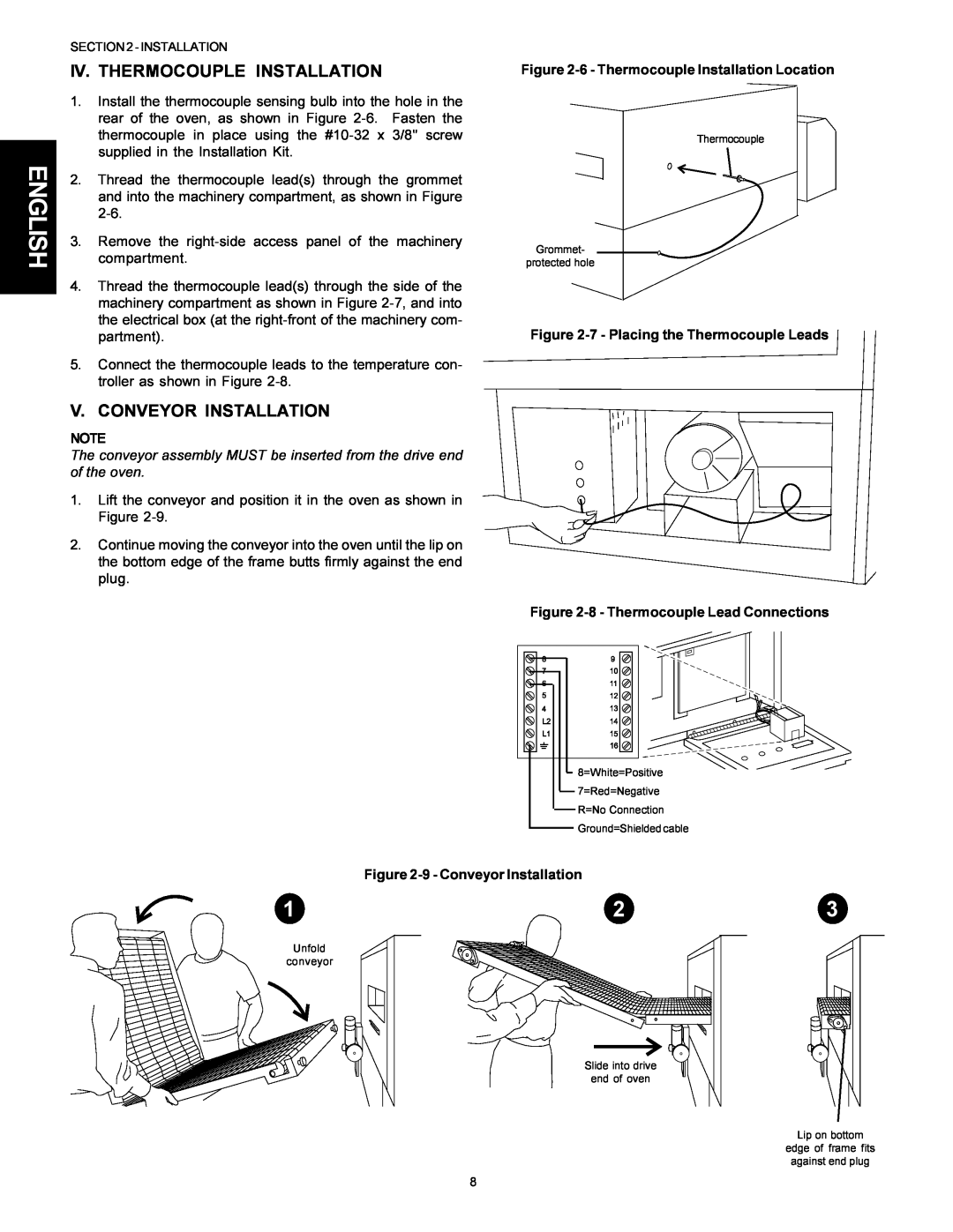
IV. THERMOCOUPLE INSTALLATION
V. CONVEYOR INSTALLATION
Figure 2-6- Thermocouple Installation Location
Figure 2-9- Conveyor Installation
ENGLISH
Figure 2-10- Drive Motor and Drive Chain
Figure 2-11- Conveyor belt tension
Figure 2-12- Master link orientation
VI. FINAL ASSEMBLY
Figure 2-13- Final Assembly - Front
Figure 2-14- Final Assembly - Rear
ENGLISH
ENGLISH
VII. ELECTRICAL SUPPLY all ovens
ENGLISH
VIII. GAS SUPPLY gas ovens only
SECTION 3 - OPERATION
ENGLISH
I.LOCATION AND DESCRIPTION OF CONTROLS
NOT SHOWN
II. NORMAL OPERATION - STEP-BY-STEP
+ or + or
DAILYSTARTUPPROCEDURE
ENGLISH
Display
V. QUICK REFERENCE TROUBLESHOOTING
SYMPTOMPROBLEM
SOLUTION
ENGLISH
SECTION 4 - MAINTENANCE
ENGLISH
I. MAINTENANCE - DAILY
II. MAINTENANCE - MONTHLY
ENGLISH
FRONT
III. MAINTENANCE - EVERY 3 MONTHS
IV. MAINTENANCE - EVERY 6 MONTHS
V. MAINTENANCE - EVERY 12 MONTHS
ENGLISH
machinery compartment or control compartment
ENGLISH page
FRANÇAIS page ESPAÑOL página
24-HourService Hotline
MANUEL D’INSTALLATION
Fours électriques et à gaz, modèle PS314SBI
ET D’UTILISATION
Modèles
Service d’assistance téléphonique 24 heures
AVERTISSEMENT
FRANÇAIS
Conservez ce manuel pour référence ultérieure
TABLE DES MATIÈRES
SECTION 2 -INSTALLATION
FRANÇAIS
page
SECTION 1 - DESCRIPTION
FRANÇAIS
II. COMPOSANTS DU FOUR - Figure
SPÉCIFICATIONS DU FOUR
SECTION 2 - INSTALLATION
FRANÇAIS
AVERTISSEMENT
AVERTISSEMENT
I. TROUSSE DINSTALLATION
II. SYSTÈME DE VENTILATION
FRANÇAIS
MISE EN GARDE
FRANÇAIS
III. ASSEMBLAGE
IV. INSTALLATION DU THERMOCOUPLE
V. INSTALLATION DU TRANSPORTEUR
Figure 2-6- Point dinstallation du thermocouple
Figure 2-9- Installation du transporteur
REMARQUE
Figure 2-10- Moteur dentraînement et chaîne
dentraînement
FRANÇAIS
FRANÇAIS
VI. ASSEMBLAGE FINAL
Figure 2-13- Assemblage final - Avant
Figure 2-14- Assemblage final - Arrière
MISE EN GARDE
FRANÇAIS
VII. ALIMENTATION EN ÉLECTRICITÉ tous les fours
AVERTISSEMENT
FRANÇAIS
VIII. ALIMENTATION EN GAZ fours à gaz seulement
MISE EN GARDE
AVERTISSEMENT
SECTION 3 - OPÉRATION
I.EMPLACEMENT ET DESCRIPTION DES COMMANDES
FRANÇAIS
NON ILLUSTRÉ
+ ou +
II. OPÉRATION NORMALE - PAS-À-PAS
MISE EN GARDE
FRANÇAIS
FRANÇAIS
Témoin OVERTEMP
SOLUTION
FRANÇAIS
V. CONSULTATION RAPIDE DÉPANNAGE
SYMPTÔME
SECTION 4 - ENTRETIEN
FRANÇAIS
FRANÇAIS
I. ENTRETIEN - QUOTIDIEN
MISE EN GARDE
II. ENTRETIEN - MENSUEL
FRANÇAIS
III. ENTRETIEN - TRIMESTRIEL
IV. ENTRETIEN - SEMESTRIEL
V. ENTRETIEN - ANNUEL
du compartiment des composants ou de commande
Service dassistance téléphonique 24 heures
21 ESPAÑOL página
ENGLISH page
Hornos de Gas y Eléctricos Modelo PS314SBI
MANUAL DE OPERACIÓN
DEL PROPIETARIO
E INSTALACIÓN
Retenga este Manual para referencia futura
AVISO
ESPAÑOL
ÍNDICE DE MATERIAS
ESPAÑOL
página
página
SECCIÓN 1 - DESCRIPCIÓN
ESPAÑOL
I.USO DEL HORNO
II.COMPONENTES DEL HORNO - VER FIGURA
SECCIÓN 2 - INSTALACIÓN
ESPAÑOL
AVISO
AVISO
I. JUEGO DE INSTALACIÓN
II. SISTEMA DE VENTILACIÓN
Fig. 2-1- Juego de Instalación
A.Componentes del juego de instalación
C.Otros problemas de ventilación
III. ENSAMBLADO
A.Instalación de las patas o ruedas
B.Instalación del cable de sujeción
ESPAÑOL
IV. INSTALACIÓN DEL TERMOPAR
V. INSTALACIÓN DEL TRANSPORTADOR
NOTA
ESPAÑOL
NOTA
Figura 2-11- Tensión de la banda de transporte
Figura 2-12- Orientación del Eslabón Maestro
ESPAÑOL
VI. ENSAMBLADO FINAL
Figura 2-13- Ensamblado final - Parte delantera
Figura 2-14- Ensamblado final - Parte posterior
PRECAUCIÓN
ESPAÑOL
VII. SUMINISTRO ELÉCTRICO todos los hornos
AVISO
ESPAÑOL
VIII. SUMINISTRO DE GAS solamente hornos de gas
PRECAUCIÓN
AVISO
SECCIÓN 3 - OPERACIÓN
ESPAÑOL
I.UBICACIÓN Y DESCRIPCIÓN DE LOS CONTROLES
NO MOSTRADO
+ o + o
ESPAÑOL
II. OPERACIÓN NORMAL - PASO A PASO IMPORTANTE
IMPORTANTE
ESPAÑOL
Luz “SP LOCK”
PROBLEMA
ESPAÑOL
V. REFERENCIA RÁPIDA DIAGNÓSTICO DE AVERÍAS
SÍNTOMA
SECCIÓN4-MANTENIMIENTO
ESPAÑOL
ESPAÑOL
I. MANTENIMIENTO - DIARIO
PRECAUCIÓN
PARTE DELANTERA
ESPAÑOL
III. MANTENIMIENTO - TRIMESTRAL
IV. MANTENIMIENTO - SEMESTRAL
V. MANTENIMIENTO - ANUAL
IMPORTANTE
Top
Page
Image
Contents