USER GUIDE
6. DX User IP front panel
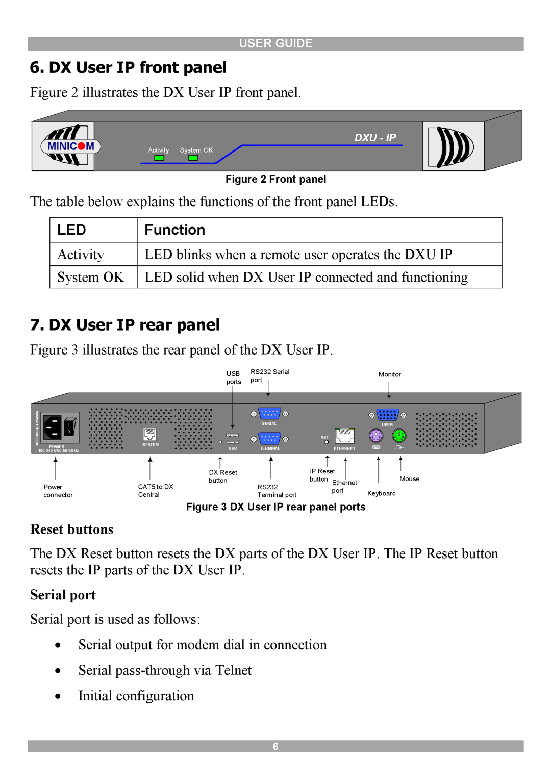
Figure 2 illustrates the DX User IP front panel.
MINICOM |
| DXU - IP |
Activity | System OK |
Figure 2 Front panel
The table below explains the functions of the front panel LEDs.
LED | Function |
|
|
Activity | LED blinks when a remote user operates the DXU IP |
|
|
System OK | LED solid when DX User IP connected and functioning |
|
|
7. DX User IP rear panel
Figure 3 illustrates the rear panel of the DX User IP.
|
| USB | RS232 Serial | Monitor |
|
| ports | port |
|
www. |
|
|
|
|
minicom | I |
| SERIAL | USER |
0 |
|
|
| |
|
|
| RST | |
.com |
|
|
| |
POWER | SYSTEM |
|
| |
USB | TERMINAL | ETHERNET | ||
|
|
| ||
|
|
|
|
|
|
|
|
|
|
|
|
| |
|
|
|
|
|
|
|
|
|
|
|
|
| |
|
|
| DX | Reset |
| IP Reset |
|
|
|
| |||
|
|
|
| Mouse | |||||||||
|
|
| button |
| button |
|
|
| |||||
|
|
| Ethernet |
| |||||||||
Power |
|
|
| ||||||||||
CAT5 to DX | RS232 | port | Keyboard | ||||||||||
connector | Central | Terminal port | |||||||||||
|
| ||||||||||||
Figure 3 DX User IP rear panel ports
Reset buttons
The DX Reset button resets the DX parts of the DX User IP. The IP Reset button resets the IP parts of the DX User IP.
Serial port
Serial port is used as follows:
∙Serial output for modem dial in connection
∙Serial
∙Initial configuration
6