9
MICROPROCESSOR CONTROL
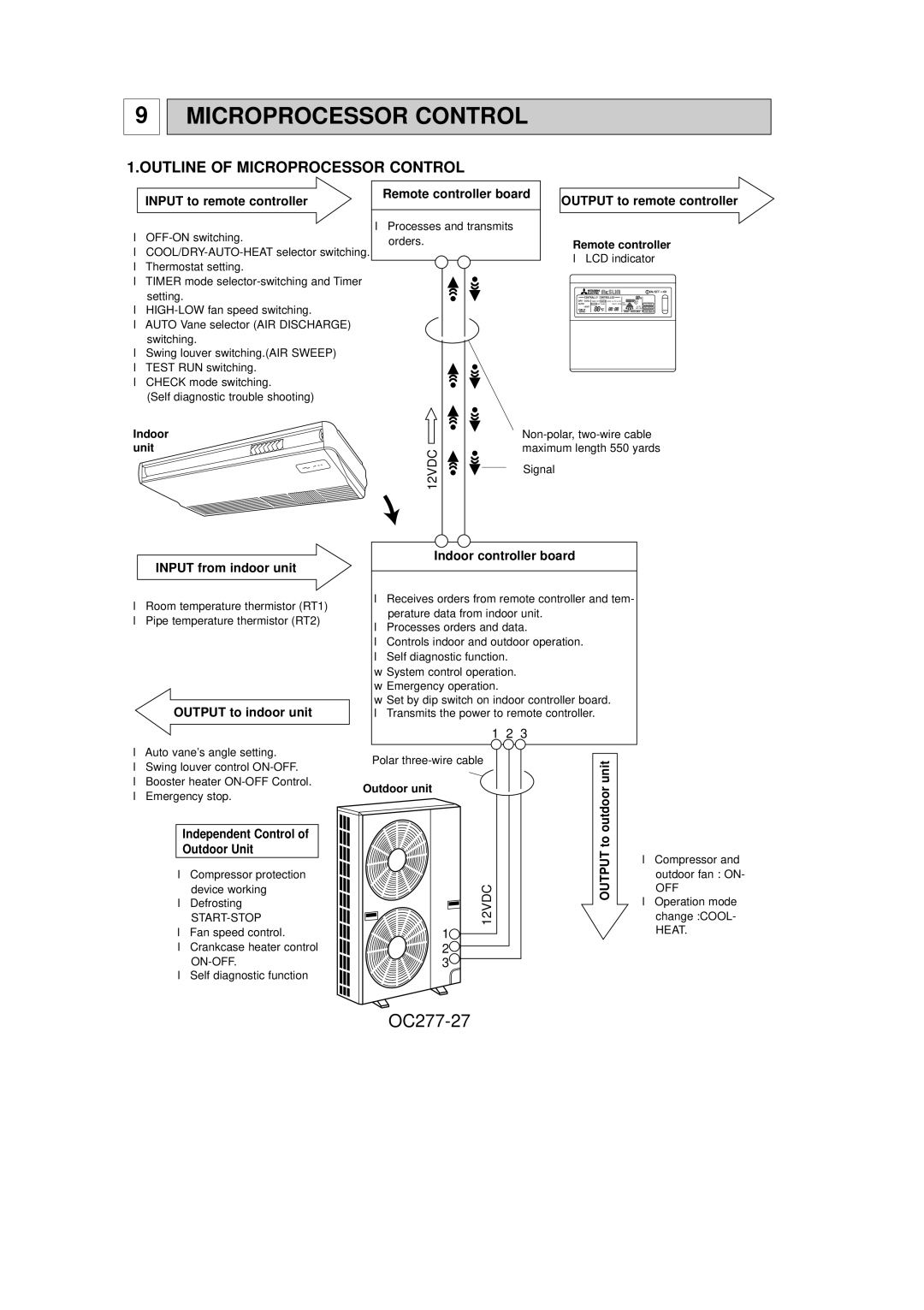
1.OUTLINE OF MICROPROCESSOR CONTROL
INPUT to remote controller | Remote controller board | OUTPUT to remote controller |
|
●
●
●Thermostat setting.
●TIMER mode
●
●AUTO Vane selector (AIR DISCHARGE) switching.
●Swing louver switching.(AIR SWEEP)
●TEST RUN switching.
●CHECK mode switching.
(Self diagnostic trouble shooting)
●Processes and transmits orders.
Remote controller
●LCD indicator
TIMER OFF TIMER | CLOCK AUTO AUTO | FAN |
|
CHECK SET TEMP. | START STOP | SPEED | FILTER |
|
| AUTO | CHECK MODE |
|
| RETURN |
TEST RUN
Indoor |
|
unit | 12VDC |
|
Signal
INPUT from indoor unit
●Room temperature thermistor (RT1)
●Pipe temperature thermistor (RT2)
OUTPUT to indoor unit
Indoor controller board
●Receives orders from remote controller and tem- perature data from indoor unit.
●Processes orders and data.
●Controls indoor and outdoor operation.
●Self diagnostic function.
wSystem control operation.
wEmergency operation.
wSet by dip switch on indoor controller board. ● Transmits the power to remote controller.
1 2 3
●Auto vane’s angle setting.
●Swing louver control
●Booster heater
●Emergency stop.
Independent Control of
Outdoor Unit
●Compressor protection device working
●Defrosting
START-STOP
●Fan speed control.
●Crankcase heater control
●Self diagnostic function
Polar
Outdoor unit
12VDC |
1 |
2 |
3 |
OUTPUT to outdoor unit
●Compressor and outdoor fan : ON-
OFF
●Operation mode change :COOL- HEAT.
