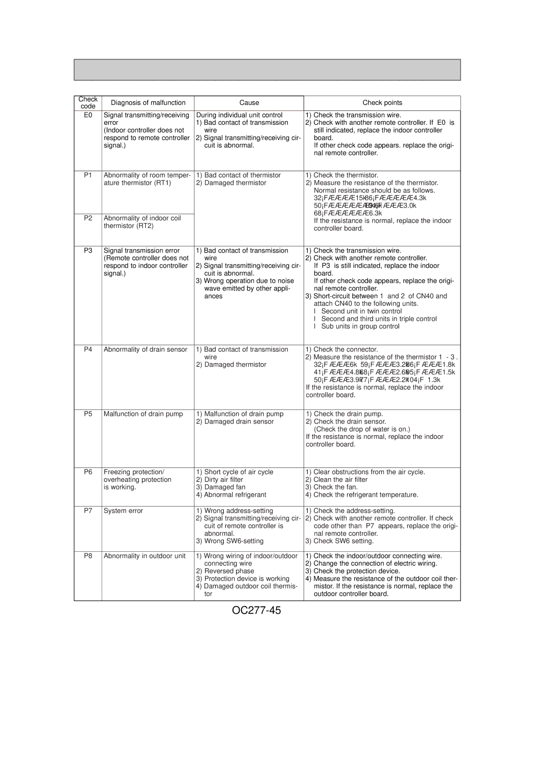
Check | Diagnosis of malfunction |
| Cause |
|
| Check points |
|
code |
|
|
|
| |||
|
|
|
|
|
|
| |
E0 | Signal transmitting/receiving | During individual unit control | 1) | Check the transmission wire. |
| ||
| error | 1) Bad contact of transmission | 2) | Check with another remote controller. If “E0” is | |||
| (Indoor controller does not |
| wire |
| still indicated, replace the indoor controller | ||
| respond to remote controller | 2) Signal transmitting/receiving cir- |
| board. |
|
| |
| signal.) |
| cuit is abnormal. |
| If other check code appears. replace the origi- | ||
|
|
|
|
| nal remote controller. |
| |
|
|
|
|
|
|
| |
P1 | Abnormality of room temper- | 1) | Bad contact of thermistor | 1) | Check the thermistor. |
| |
| ature thermistor (RT1) | 2) | Damaged thermistor | 2) Measure the resistance of the thermistor. | |||
|
|
|
|
| Normal resistance should be as follows. | ||
|
|
|
|
| 32°F····15kΩ | 86°F·····4.3kΩ | |
|
|
|
|
| 50°F······9.6kΩ | 104°F ···3.0kΩ | |
|
|
|
|
| 68°F······6.3kΩ |
|
|
P2 | Abnormality of indoor coil |
|
|
|
|
| |
|
|
| If the resistance is normal, replace the indoor | ||||
| thermistor (RT2) |
|
|
| |||
|
|
|
| controller board. |
| ||
|
|
|
|
|
| ||
|
|
|
|
|
| ||
P3 | Signal transmission error | 1) Bad contact of transmission | 1) | Check the transmission wire. |
| ||
| (Remote controller does not |
| wire | 2) | Check with another remote controller. | ||
| respond to indoor controller | 2) Signal transmitting/receiving cir- |
| If “P3” is still indicated, replace the indoor | |||
| signal.) |
| cuit is abnormal. |
| board. |
|
|
|
| 3) Wrong operation due to noise |
| If other check code appears, replace the origi- | |||
|
|
| wave emitted by other appli- |
| nal remote controller. |
| |
|
|
| ances | 3) | |||
|
|
|
|
| attach CN40 to the following units. | ||
|
|
|
|
| ● Second unit in twin control |
| |
|
|
|
|
| ● Second and third units in triple control | ||
|
|
|
|
| ● Sub units in group control |
| |
|
|
|
|
|
| ||
P4 | Abnormality of drain sensor | 1) Bad contact of transmission | 1) | Check the connector. |
| ||
|
|
| wire | 2) | Measure the resistance of the thermistor 1 - 3. | ||
|
| 2) | Damaged thermistor |
| 32°F ···6kΩ | 59°F ···3.2kΩ | 86°F ···1.8kΩ |
|
|
|
|
| 41°F ···4.8kΩ | 68°F ···2.6kΩ | 95°F ···1.5kΩ |
|
|
|
|
| 50°F ···3.9kΩ | 77°F ···2.2kΩ | 104°F 1.3kΩ |
|
|
|
| If the resistance is normal, replace the indoor | |||
|
|
|
| controller board. |
|
| |
|
|
|
|
|
| ||
P5 | Malfunction of drain pump | 1) | Malfunction of drain pump | 1) Check the drain pump. |
| ||
|
| 2) | Damaged drain sensor | 2) Check the drain sensor. |
| ||
|
|
|
|
| (Check the drop of water is on.) | ||
|
|
|
| If the resistance is normal, replace the indoor | |||
|
|
|
| controller board. |
|
| |
|
|
|
|
|
| ||
P6 | Freezing protection/ | 1) | Short cycle of air cycle | 1) | Clear obstructions from the air cycle. | ||
| overheating protection | 2) | Dirty air filter | 2) | Clean the air filter |
| |
| is working. | 3) | Damaged fan | 3) | Check the fan. |
|
|
|
| 4) Abnormal refrigerant | 4) | Check the refrigerant temperature. | |||
|
|
|
|
|
|
| |
P7 | System error | 1) | Wrong | 1) | Check the |
| |
|
| 2) Signal transmitting/receiving cir- | 2) | Check with another remote controller. If check | |||
|
|
| cuit of remote controller is |
| code other than “P7” appears, replace the origi- | ||
|
|
| abnormal. |
| nal remote controller. |
| |
|
| 3) | Wrong | 3) | Check SW6 setting. |
| |
|
|
|
|
| |||
P8 | Abnormality in outdoor unit | 1) Wrong wiring of indoor/outdoor | 1) | Check the indoor/outdoor connecting wire. | |||
|
|
| connecting wire | 2) | Change the connection of electric wiring. | ||
|
| 2) | Reversed phase | 3) | Check the protection device. |
| |
|
| 3) | Protection device is working | 4) | Measure the resistance of the outdoor coil ther- | ||
|
| 4) Damaged outdoor coil thermis- |
| mistor. If the resistance is normal, replace the | |||
|
|
| tor |
| outdoor controller board. |
| |
|
|
|
|
|
|
|
|
