10 |
|
| TROUBLE SHOOTING |
|
|
|
|
|
| ||
|
|
|
|
|
|
|
|
|
| ||
1. REMOTE CONTROLLER DISPLAY ABNORMALITY |
|
|
|
|
|
| |||||
|
|
|
|
|
|
|
|
| |||
Display abnormality |
| Cause |
|
| Check points |
|
| ||||
|
|
|
|
|
|
| |||||
The display “centrally con- | 1) | Wrong address setting of remote con- | 1) Check the address setting of remote controller | ||||||||
trolled” on remote con- |
| troller/indoor controller board. | and indoor controller. |
|
| ||||||
troller does not disappear. | 2) Timer adapter is connected to the | 2) Check if the timer adapter is used correctly. | |||||||||
|
|
|
|
| remote controller. | 3) 1 Turn another remote controller’s DIP SW17- | |||||
|
|
|
| 3) | Signal transmission error between |
| 7 ON to make it sub controller. | ||||
|
|
|
|
| indoor unit and remote controller. | 2 Connect the sub controller to the unit, and | |||||
|
|
|
|
|
|
| turn circuit breaker ON. |
|
| ||
|
|
|
|
|
| ● If the display “centrally controlled” disap- | |||||
|
|
|
|
|
|
| pears, replace the original remote controller. | ||||
|
|
|
|
|
| ● If the display remains the same, replace the | |||||
|
|
|
|
|
|
| indoor controller board. |
|
| ||
|
|
|
|
|
|
| |||||
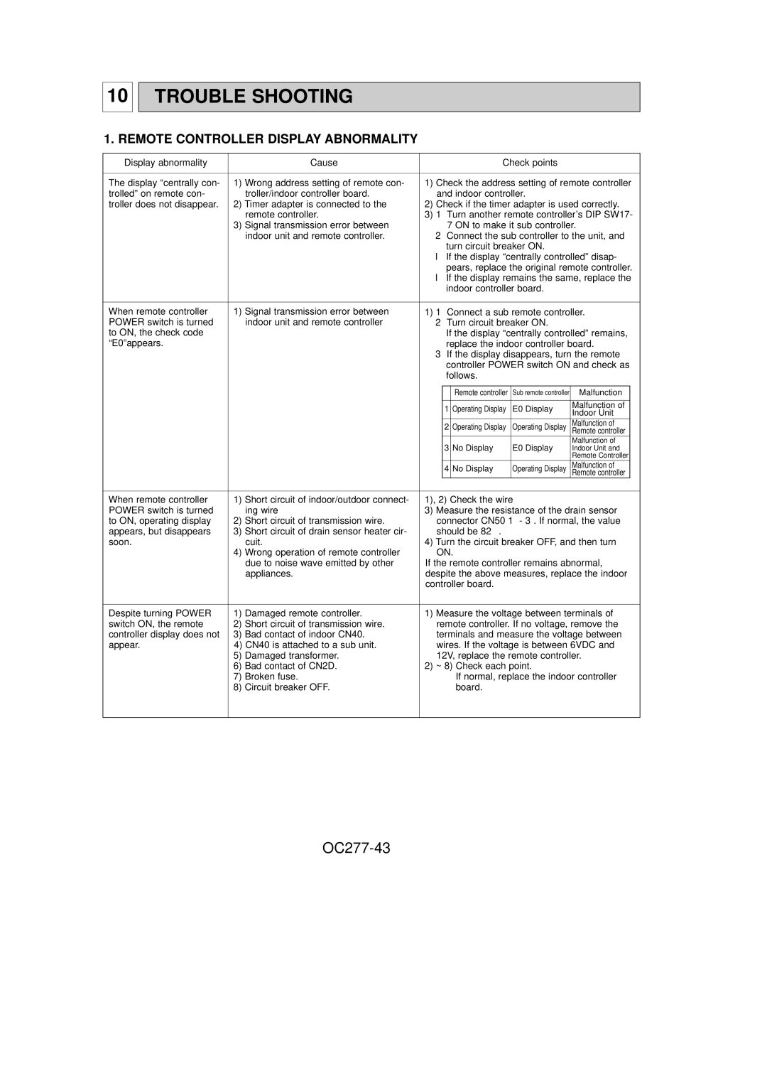
When remote controller | 1) | Signal transmission error between | 1) 1 Connect a sub remote controller. | ||||||||
POWER switch is turned |
| indoor unit and remote controller | 2 Turn circuit breaker ON. |
|
| ||||||
to ON, the check code |
|
|
| If the display “centrally controlled” remains, | |||||||
“E0”appears. |
|
|
| replace the indoor controller board. | |||||||
|
|
|
|
|
| 3 If the display disappears, turn the remote | |||||
|
|
|
|
|
|
| controller POWER switch ON and check as | ||||
|
|
|
|
|
|
| follows. |
|
|
| |
|
|
|
|
|
|
|
|
|
|
|
|
|
|
|
|
|
|
|
| Remote controller | Sub remote controller | Malfunction |
|
|
|
|
|
|
|
|
|
|
|
|
|
|
|
|
|
|
|
| 1 | Operating Display | E0 Display | Malfunction of |
|
|
|
|
|
|
|
| Indoor Unit |
| |||
|
|
|
|
|
|
|
|
|
|
| |
|
|
|
|
|
|
| 2 | Operating Display | Operating Display | Malfunction of |
|
|
|
|
|
|
|
| Remote controller |
| |||
|
|
|
|
|
|
| 3 | No Display | E0 Display | Malfunction of |
|
|
|
|
|
|
|
| Indoor Unit and |
| |||
|
|
|
|
|
|
|
|
|
| Remote Controller |
|
|
|
|
|
|
|
| 4 | No Display | Operating Display | Malfunction of |
|
|
|
|
|
|
|
| Remote controller |
| |||
|
|
|
|
|
|
|
| ||||
When remote controller | 1) | Short circuit of indoor/outdoor connect- | 1), 2) Check the wire |
|
| ||||||
POWER switch is turned |
| ing wire | 3) Measure the resistance of the drain sensor | ||||||||
to ON, operating display | 2) | Short circuit of transmission wire. | connector CN50 1 - 3. If normal, the value | ||||||||
appears, but disappears | 3) | Short circuit of drain sensor heater cir- | should be 82Ω . |
|
|
| |||||
soon. |
|
| cuit. | 4) Turn the circuit breaker OFF, and then turn | |||||||
|
|
|
| 4) | Wrong operation of remote controller | ON. |
|
|
| ||
|
|
|
|
| due to noise wave emitted by other | If the remote controller remains abnormal, | |||||
|
|
|
|
| appliances. | despite the above measures, replace the indoor | |||||
|
|
|
|
|
| controller board. |
|
|
| ||
|
|
|
|
|
|
| |||||
Despite turning POWER | 1) | Damaged remote controller. | 1) Measure the voltage between terminals of | ||||||||
switch ON, the remote | 2) | Short circuit of transmission wire. | remote controller. If no voltage, remove the | ||||||||
controller display does not | 3) | Bad contact of indoor CN40. | terminals and measure the voltage between | ||||||||
appear. |
| 4) CN40 is attached to a sub unit. | wires. If the voltage is between 6VDC and | ||||||||
|
|
|
| 5) | Damaged transformer. | 12V, replace the remote controller. | |||||
|
|
|
| 6) | Bad contact of CN2D. | 2) ~ 8) Check each point. |
|
| |||
|
|
|
| 7) | Broken fuse. |
|
| If normal, replace the indoor controller | |||
|
|
|
| 8) | Circuit breaker OFF. |
|
| board. |
|
|
|
|
|
|
|
|
|
|
|
|
|
|
|