OPERATING PROCEDURE | PHOTOS&ILLUSTRATIONS |
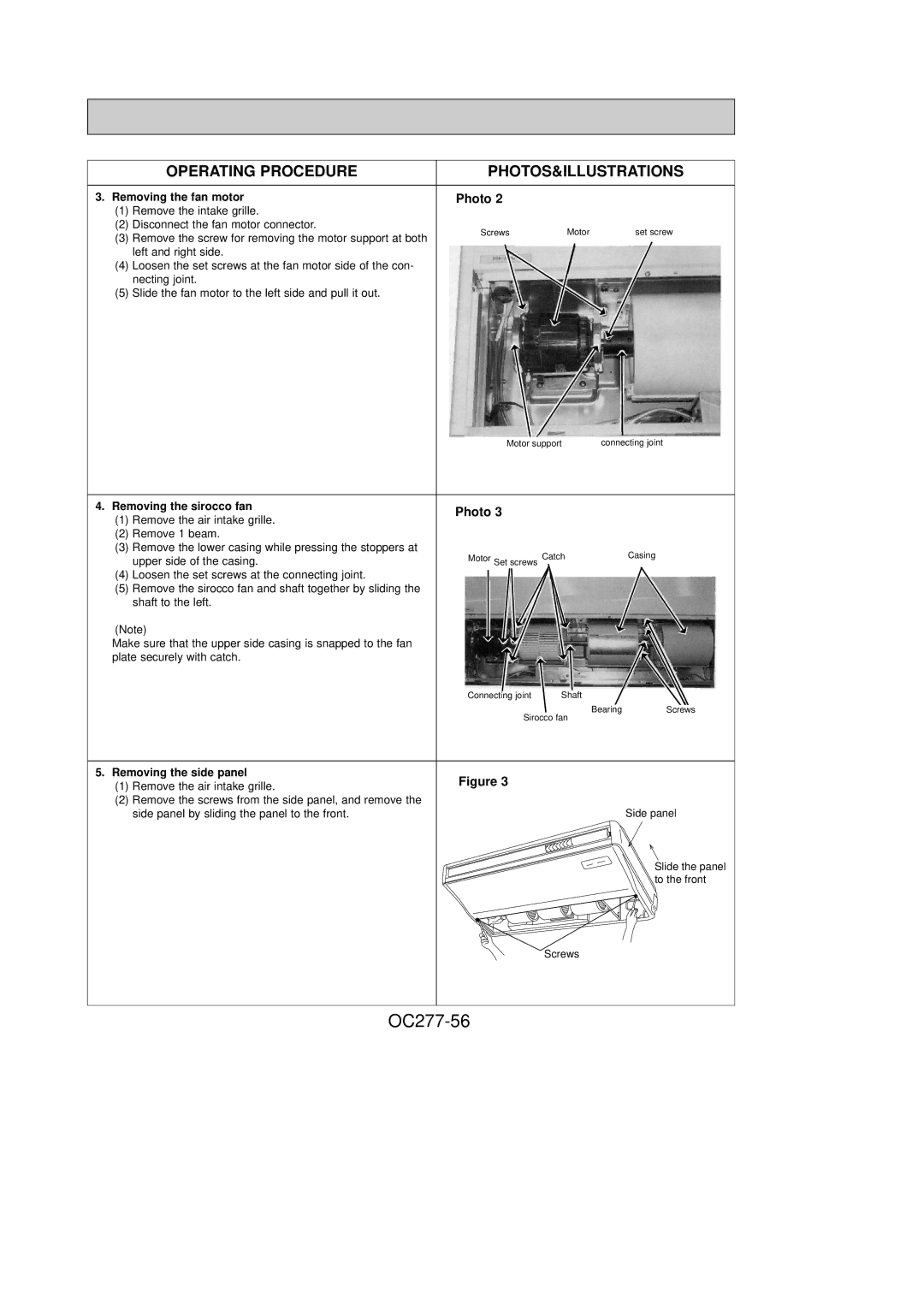
3. Removing the fan motor | Photo 2 |
(1)Remove the intake grille.
(2)Disconnect the fan motor connector.
(3) | Remove the screw for removing the motor support at both | Screws | Motor | set screw |
|
|
| ||
| left and right side. |
|
|
|
(4) | Loosen the set screws at the fan motor side of the con- |
|
|
|
| necting joint. |
|
|
|
(5) | Slide the fan motor to the left side and pull it out. |
|
|
|
Motor support | connecting joint |
4. Removing the sirocco fan | Photo 3 |
|
| ||||
(1) | Remove the air intake grille. |
|
| ||||
|
|
|
|
|
| ||
(2) | Remove 1 beam. |
|
|
|
|
|
|
(3) | Remove the lower casing while pressing the stoppers at |
|
|
|
|
|
|
|
|
|
|
|
| ||
|
|
|
|
| Casing | ||
|
|
|
| Set screws | Catch |
| |
| upper side of the casing. |
| Motor | ||||
|
|
|
|
|
| ||
|
|
|
|
|
|
|
|
|
|
|
|
|
|
|
|
(4)Loosen the set screws at the connecting joint.
(5)Remove the sirocco fan and shaft together by sliding the shaft to the left.
(Note)
Make sure that the upper side casing is snapped to the fan plate securely with catch.
Connecting joint | Shaft |
BearingScrews
Sirocco fan
5. Removing the side panel | Figure 3 | ||
(1) | Remove the air intake grille. | ||
| |||
(2) | Remove the screws from the side panel, and remove the |
| |
| side panel by sliding the panel to the front. | Side panel | |
|
| Slide the panel | |
|
| to the front | |
Screws
