3. CONTROL USING TWO REMOTE CONTROLLERS
Two remote controllers can be used to control either one unit or a group of units. Units operate according to the latest com- mand from either of the two remote controllers.
Before operation, be sure to set one remote controller as the “main controller” and the other as the “sub controller”, using dip switch
Figure 4
Individual |
operation |
Remote |
controller |
Remote |
controller |
![]() Multiple operation
Multiple operation
Remote |
controller |
Remote controller
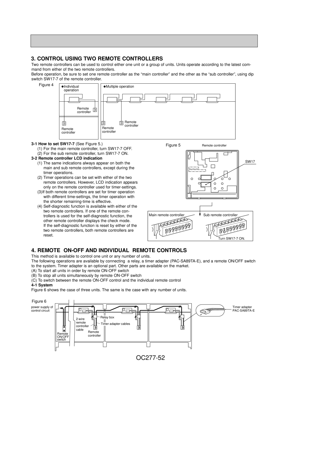
3-1 How to set SW17-7 (See Figure 5.)
(1)For the main remote controller, turn
(2)For the sub remote controller, turn
3-2 Remote controller LCD indication
(1)The same indications always appear on both the main and sub remote controllers, except during the timer operations.
(2)Timer operations can be set with either of the two remote controllers. However, LCD indication appears only on the remote controller used for
(3)If both remote controllers are set for timer operation with different
(4)
If the
Figure 5
Main remote controller
O F | F |
| 1 |
3 | 2 |
4 |
|
5 |
|
6 |
|
7 |
|
8
Remote controller
SW17
Sub remote controller
O F | F |
| 1 |
3 | 2 |
4 |
|
5 6 7 8
Turn
4. REMOTE ON-OFF AND INDIVIDUAL REMOTE CONTROLS
This method is available to control one unit or any number of units.
The following operations are available by connecting a relay, a timer adapter
(A)To start all units in order by remote
(B)To stop all units simultaneously by remote
(C)To switch between the remote
4-1 System
Figure 6 shows the case of three units. The same is the case with any number of units.
Figure 6
power supply of control circuit
Remote |
ON/OFF |
switch |
Relay box | |
| |
remote | Timer adapter cables |
| |
controller | |
cable | Remote |
| |
| controller |
|
|
Timer adapter ![]()
![]()