5
OUTLINES AND DIMENSIONS
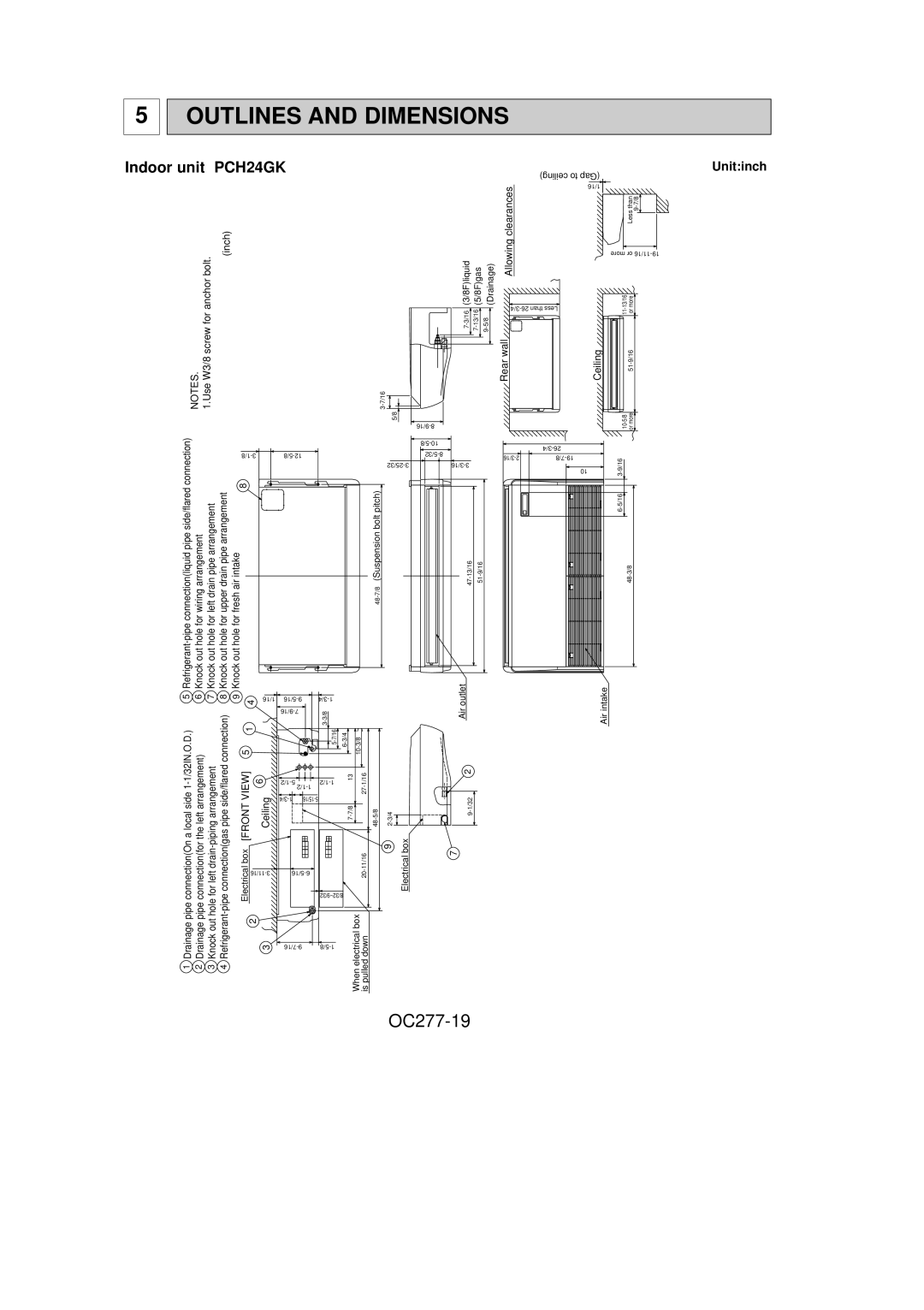
Indoor unit PCH24GK
anchorforscrewbolt. | (inch) | ||
|
| (5/8F)gas | (Drainage) |
NOTES. 1.Use W3/8 |
|
| |
| 5/8 |
|
|
|
|
|
Unit:inch
| ceiling) to (Gap |
|
| |
clearances | 1/16 |
|
| |
|
| Less than | ||
Allowing |
| more or | ||
|
| |||
13/16 | more | |||
11- or | ||||
|
| |||
Rear wall | Ceiling |
| ||
|
| or more | ||
connection) | |
8 |
| |
| |
|
| |
| 10 | |
|
| 3 |
Knock out hole for wiring arrangement | Knock out hole for left drain pipe arrangement | Knock out hole for upper drain pipe arrangement | Knock out hole for fresh air intake |
| |
5 6 7 8 9 | 1/16 | ||||
|
|
|
| 4 | |
|
|
|
|
| |
Drainagepipe connection(On a local side |
|
| 1 |
| |
Drainagepipe connection(for the left arrangement) | Knockout hole for left |
| 6 | ||
| Ceiling | ||||
[FRONTElectricalVIEW]box5 2 | 3 | ||||
1 2 3 4 |
|
| |||
|
|
|
| ||
|
|
|
| ||
|
|
|
|
| |
|
|
| |||
|
|
| 10 |
|
|
13 | 1/16 |
|
| ||
| - |
|
| ||
|
|
| 27 |
|
|
|
|
|
| ||
|
|
| |||
|
|
| 9 | box | |
|
| Electrical | |||
|
|
|
| ||
| 8/32~9/32 |
|
|
| |
|
|
| box |
|
|
| electricalWhen downpulledis |
|
| ||
|
|
|
| ||
Air outlet
7
Air intake