12 
 DISASSEMBLY PROCEDURE
PCH24GK
OPERATING PROCEDURE | PHOTOS&ILLUSTRATIONS |
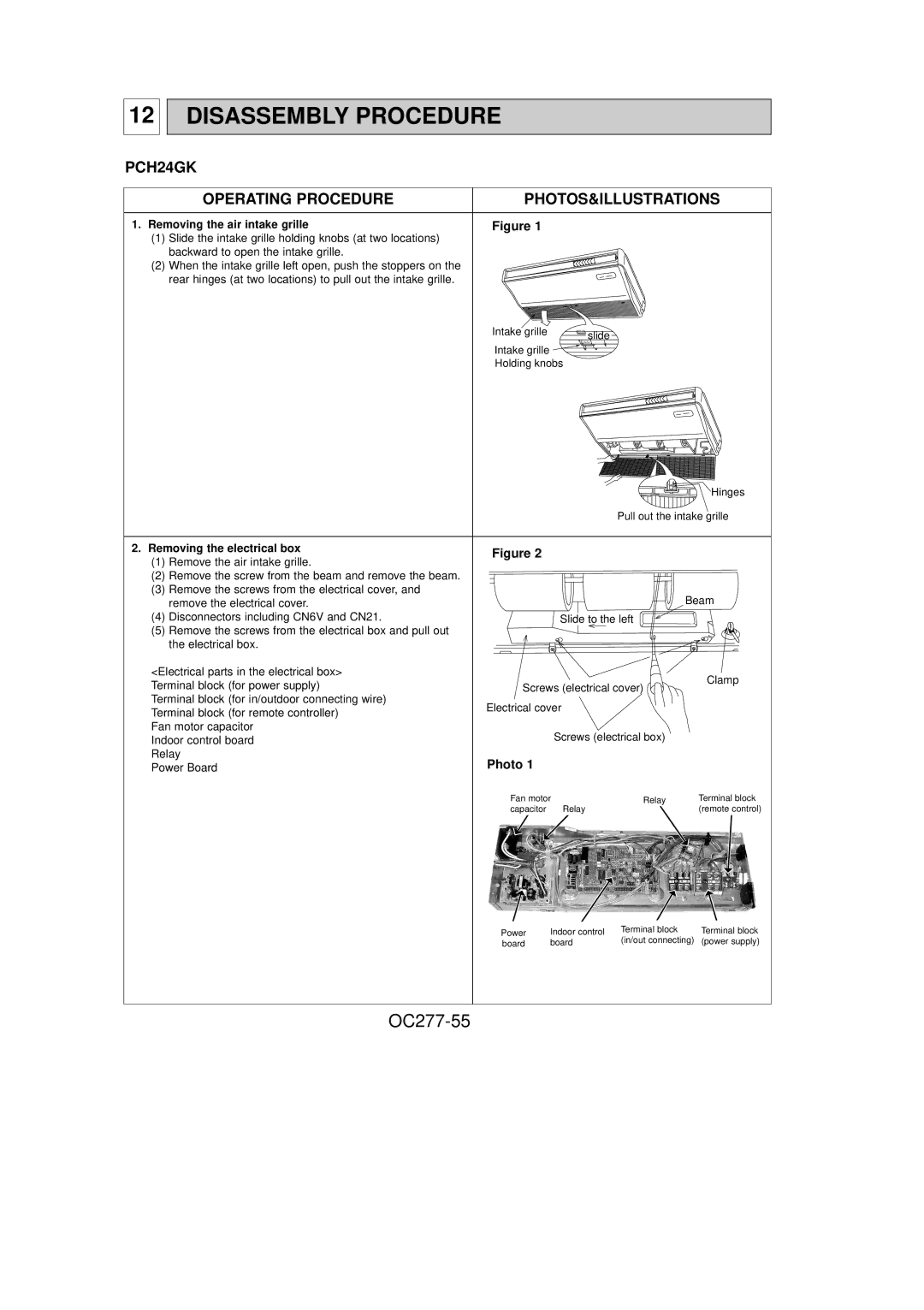
1. Removing the air intake grille | Figure 1 |
(1)Slide the intake grille holding knobs (at two locations) backward to open the intake grille.
(2) When the intake grille left open, push the stoppers on the rear hinges (at two locations) to pull out the intake grille.
Intake grille | slide |
|
Intake grille
Holding knobs
Hinges
Pull out the intake grille
2. Removing the electrical box | Figure 2 |
(1)Remove the air intake grille.
(2)Remove the screw from the beam and remove the beam.
(3)Remove the screws from the electrical cover, and
remove the electrical cover. |
|
| Beam | |
(4) Disconnectors including CN6V and CN21. |
| Slide to the left |
| |
(5) Remove the screws from the electrical box and pull out |
|
|
| |
the electrical box. |
|
|
| |
<Electrical parts in the electrical box> |
|
| Clamp | |
Terminal block (for power supply) | Screws (electrical cover) | |||
| ||||
Terminal block (for in/outdoor connecting wire) | Electrical cover |
| ||
Terminal block (for remote controller) |
| |||
|
|
| ||
Fan motor capacitor |
| Screws (electrical box) |
| |
Indoor control board |
|
| ||
Relay | Photo 1 |
|
| |
Power Board |
|
| ||
| Fan motor | Relay | Terminal block | |
| capacitor | Relay | (remote control) | |
Power | Indoor control | Terminal block | Terminal block |
board | board | (in/out connecting) | (power supply) |