BWB400-SERIES
INSTALLATION, OPERATION AND MAINTENANCE MANUAL
BWB400, BWB400I, BWBC400 AND
BWBC400I WOOD BURNING FIREPLACES
TABLE OF CONTENTS
CONGRATULATIONS
LISTING AND CODE APPROVALS
4. Leakage of rain water into the dwelling
IMPORTANT INFORMATION
1. Damage to the fireplace from overheating
3. The emission of smoke, sparks or hazardous gases into the dwelling
OPERATION GUIDELINES
CLEARANCES
RESIDENTIAL INSTALLATION
OPERATION GUIDELINES
CLEARANCES
OUTSIDE AIR CONNECTOR CENTERLINE 13 1/8 TOP VIEW
CAUTION Do not install fireplace over carpeting
FIREPLACE LOCATION
INSTALLATION PREPARATION
INSTALLATION PREPARATION
SINGLE STORY INSTALLATION WITH ATTIC SPACE
MULTIPLE STORY INSTALLATION
FLOOR PROTECTION
C=K divided by the material thickness Example C = .43 divided by 1/2
FLOOR PROTECTION
FIREPLACE COMPONENTS
R3672 36
R4884 48
FIREPLACE COMPONENTS
MODEL
DESCRIPTION
FIREPLACE INSTALLATION
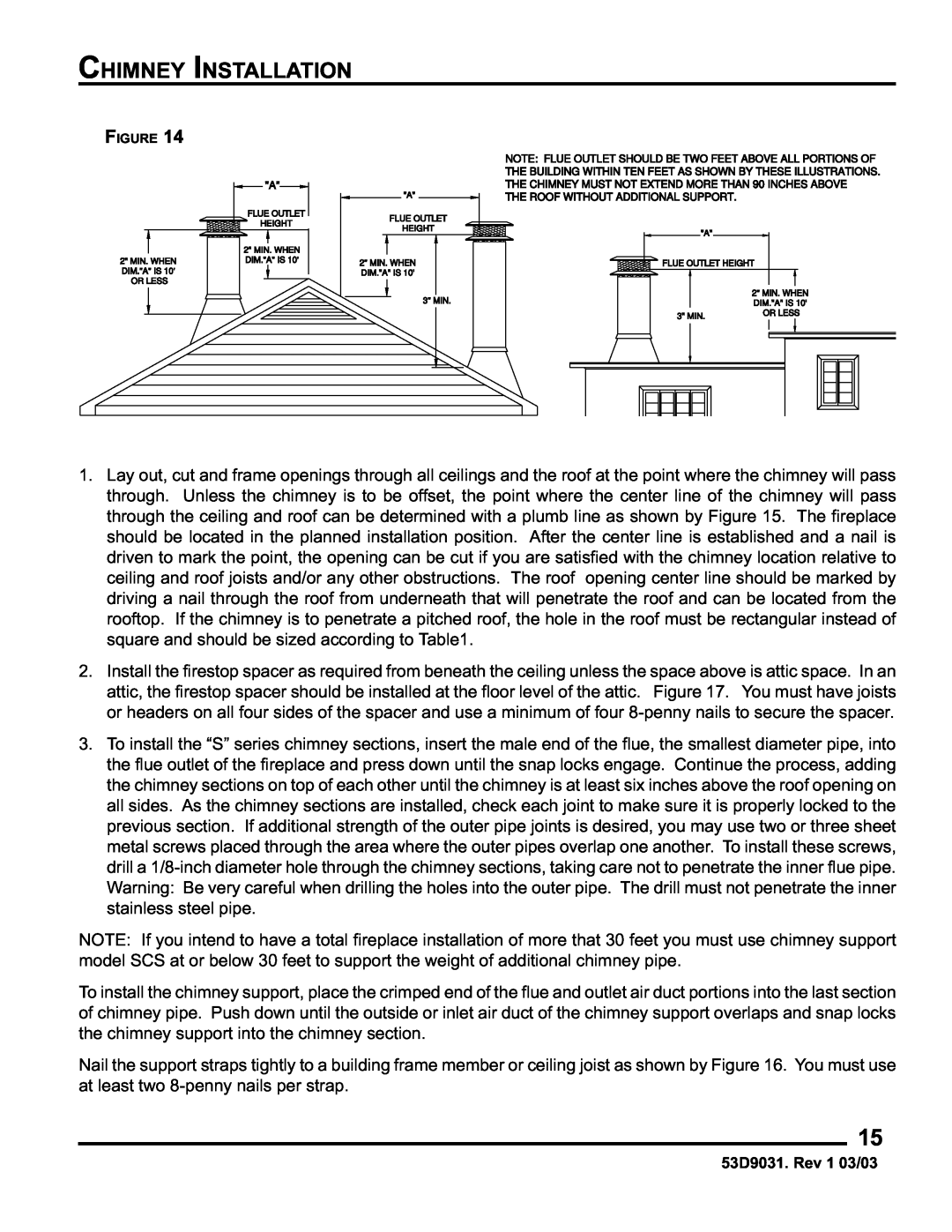
CHIMNEY INSTALLATION
0/12
CHIMNEY INSTALLATION
CHIMNEY OFFSET INSTALLATION
30 ˚
CHIMNEY OFFSET AND CAP INSTALLATION
14-1/2
22-1/16
CHIMNEY CAP INSTALLATION
CHIMNEY HEIGHT AND OFFSET CHARTS
FLAT FLASHING OR CHASE COVER WITH 11-1/4 MIN. DIA. HOLE
CHIMNEY CAP CHASE INSTALLATION
CHIMNEY CAP SUPPORT BRACKETS. 3 PLACES SCREW MAINTAIN CHIMNEY
SYSTEM AIR SPACE CLEARANCES TO COMBUSTIBLES ABOVE ROOF LINE
OUTSIDE COMBUSTION AIR PRECAUTIONS AND RECOMMENDATIONS
OUTSIDE COMBUSTION AIR PRECAUTIONS & RECOMMENDATIONS
COMBUSTION AIR ASSEMBLY
GAS APPLIANCE INSTALLATION
IMPORTANT NOTICES
CAUTION If an unvented gas appliance is installed in the fireplace, the gas appliance must only be operated with the fireplace glass door fully open if included. Only unvented gas log set which have been found to comply with the standard for unvented room heaters, ANSI/IAS/AGA Z21.11.2, are to be installed in this fireplace
GAS APPLIANCE INSTALLATION
1 1/2
TRIM INSTALLATION
GAS APPLIANCE INSTALLATION
12 MAX
PART C
TRIM INSTALLATION
PART A
PART B
GLASS DOOR INSTALLATION AND FAN ACCESSORY
FIREPLACE OPERATION
Dogwood
FIREPLACE OPERATION
MAINTENANCE AND SAFETY
DO’S
MAINTENANCE AND SAFETY
DONT’S
MAINTENANCE AND SAFETY
BWB400/BWB400I MODEL FIREPLACE
PARTS DIAGRAM AND LIST
PARTS DIAGRAM AND LIST
BWBC400/BWBC400I
MODEL FIREPLACE
LIMITED WARRANTY
FACTORY-BUILT FIREPLACE AND COMPONENTS
EXCEPT BLOWERS
LIMITED WARRANTY
IF YOU HAVE A PROBLEM WITH YOUR FIREPLACE OR COMPONENT
YOUR DUTIES
53D9031. Rev 1 03/03
This page intentionally left blank
53D9031. Rev 1 03/03
This page intentionally left blank
53D9031. Rev 1 03/03
APPLIANCE INSTALLER
PLEASE RETURN THESE OPERATING AND INSTALLATION INSTRUCTIONS
TO THE CONSUMER
INSTALLATION, OPERATION AND MAINTENANCE MANUAL
BWB500, BWB500I, BWBC500 AND
BWBC500I RESIDENTIAL FIREPLACES
SF42 SERIES
LISTING AND CODE APPROVALS
TABLE OF CONTENTS
CONGRATULATIONS
Chimney Cap Chase Installation
IMPROPER INSTALLATION
INTENDED PRODUCT USAGE
IMPORTANT INFORMATION
OPERATION GUIDELINES
Glass doors should be installed to receive the maximum benefit from your fireplace. For large fires, the maximum heating benefit from the fireplace will be obtained with the doors open due to the high amount of radiant heat being emitted out of the front opening of the fireplace. With a small fire, or before retiring in the evenings, it is best to operate the fireplace with the doors closed to prevent excessive room air from being drawn up the chimney. When the doors are open, the mesh screens should be closed to help keep burning embers from popping out of the firebox
CLEARANCES
RESIDENTIAL INSTALLATION
53D9032. Rev 1 03/03
CLEARANCES
21 1/2 MIN
CAUTION Do not install fireplace over carpeting
WITH GLASS DOORS INSTALLED
FIREPLACE LOCATION
JOIST INSULATE SAME
INSTALLATION PREPARATION
INSTALLATION PREPARATION
SINGLE STORY INSTALLATION WITH ATTIC SPACE
53D9032. Rev 1 03/03
FLOOR PROTECTION
If this fireplace is installed on a combustible floor, the floor area 20 inches in front of, and 12 inches either side of the fireplace opening must be protected by an insulating noncombustible hearth extension. This hearth extension may be either minimum 6-inch thick stone or brick as shown by Figure 10, an H2066 Hearth Extension Kit or a locally constructed hearth equivalent to the H2066
FIREPLACE HEARTH
FLOOR METAL SAFETY STRIP
FLOOR PROTECTION
FLOOR LINE WITH RAISED HEARTH
FP-4-U
FIREPLACE COMPONENTS
GD42B OR GD42PB
SC ROUND
FIREPLACE COMPONENTS
MODEL
DESCRIPTION
FIREPLACE INSTALLATION
53D9032. Rev 1 03/03
CHIMNEY INSTALLATION
53D9032. Rev 1 03/03
CHIMNEY INSTALLATION
STRAPS MUST BE NAILED ON TO FRAMING MEMBER
CHIMNEY OFFSET INSTALLATION
REQUIRED TO BE SECURED FOR
ADDED STABILIZATION OF PIPE
14 FT
CHIMNEY OFFSET AND CAP INSTALLATION
14-1/2
22-1/16
CHIMNEY CAP INSTALLATION
53D9032. Rev 1 03/03
CHIMNEY HEIGHT AND OFFSET CHARTS
CHIMNEY CAP CHASE INSTALLATION
53D9032. Rev 1 03/03
OUTSIDE COMBUSTION AIR PRECAUTIONS & RECOMMENDATIONS
OUTSIDE COMBUSTION AIR PRECAUTIONS & RECOMMENDATIONS
COMBUSTION AIR ASSEMBLY
MODEL AK4 COMBUSTION AIR ASSEMBLY
53D9032. Rev 1 03/03
53D9032. Rev 1 03/03
GAS APPLIANCE INSTALLATION
GAS LINE PLUMBING DETAIL
GAS APPLIANCE INSTALLATION
1/4 SCREENED OPENING FINISHED WALL SCREENED OPENING OF FIREPLACE
TRIM INSTALLATION
FRAMING EXTEND LINE FROM OPPOSITE REAR OF
FIREBOX THRU A POINT 4 IN FRONT OF FIREPLACE FACE, AND 1 OUTSIDE OF
53D9032. Rev 1 03/03
GLASS DOOR INSTALLATION AND FAN ACCESSORY
GLASS DOOR INSTALLATION
FAN ASSEMBLY
WHICH WOODS ARE BEST?
HOW TO BUILD A BETTER FIRE
FIREPLACE OPERATION
ADVANTAGES OF A WOOD BURNING FIREPLACE
HEAT VALUE
FIREPLACE OPERATION
SPECIES
DENSITY
DISPOSAL OF ASHES
MAINTENANCE AND SAFETY
CHIMNEY MAINTENANCE
FUEL STORAGE
DO’S
MAINTENANCE AND SAFETY
DONT’S
MAINTENANCE AND SAFETY
BWB500 / BWB500I MODEL FIREPLACE
REPAIR PART DIAGRAMS AND LISTS
REPAIR PART DIAGRAMS AND LISTS
BWBC500 / BWBC500I MODEL FIREPLACE
LIMITED WARRANTY
FACTORY-BUILT FIREPLACE AND COMPONENTS
EXCEPT BLOWERS
LIMITED WARRANTY
Technical Service Department
2813 W. Mall Drive, Unit B. Florence, Alabama Tel
THIS PAGE INTENTIONALLY LEFT BLANK
53D9032. Rev 1 03/03
THIS PAGE INTENTIONALLY LEFT BLANK
53D9032. Rev 1 03/03
TO THE CONSUMER
PLEASE RETURN THIS OPERATING AND INSTALLATION INSTRUCTIONS
53D9032. REV 1 03/03
APPLIANCE INSTALLER