I n s t a l l a t i o n | 3 - 5 |
|
|
R F B y p a s s S w i t c h V C R C a b l i n g D i a g r a m s
Proper operation of the RF Bypass feature requires special configuration in the control system and in the EPG settings.
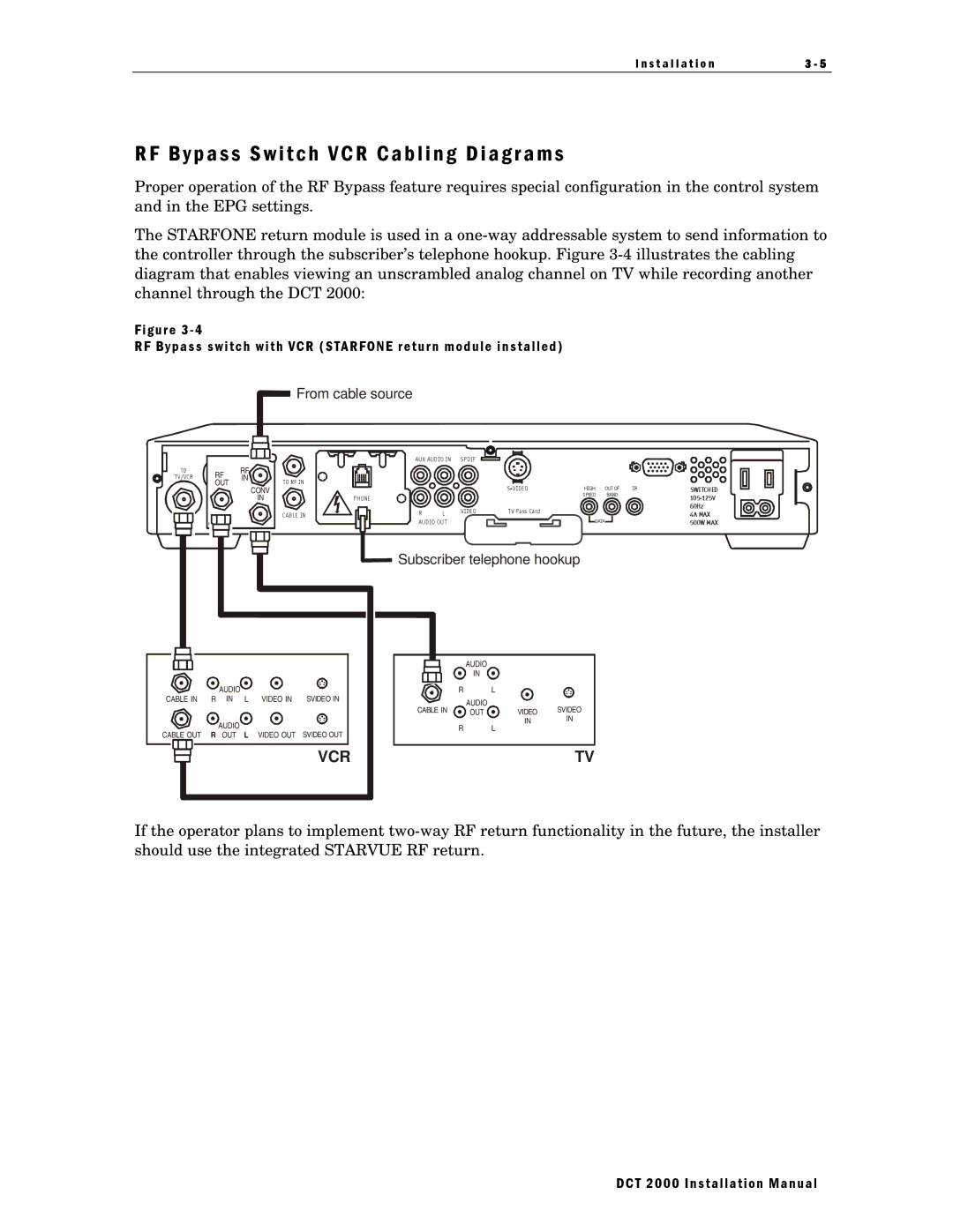
The STARFONE return module is used in a
Figure 3 - 4
RF Bypass switch with VCR (STARFONE return module installed)
![]() From cable source
From cable source
TO | RF | RF |
|
T V/VCR | IN |
| |
| OUT |
| TO RF IN |
|
|
| CONV |
| RF |
| IN |
| IN |
|
|
|
|
| CAB LE IN |
AUX AUD IO IN SPDIF
|
|
| HIGH | OUT OF | IR | SWITCHED | |
PHONE |
|
|
| SPEED | BAND |
| |
|
|
|
|
|
| ||
|
|
|
|
|
|
| 60Hz |
R | L | V IDEO | T V Pass Card |
|
|
| 4A MAX |
|
|
|
|
| |||
AUD IO OU T |
|
| DATA |
| 500W MAX | ||
|
|
|
|
| |||
![]() Subscriber telephone hookup
Subscriber telephone hookup
|
|
|
|
|
| AUDIO |
|
|
|
|
|
|
|
| IN |
|
|
|
| AUDIO |
|
| R |
| L |
|
CABLE IN | R | IN | L | VIDEO IN | SVIDEO IN | AUDIO |
|
|
|
|
|
|
| CABLE IN |
| SVIDEO | |
|
|
|
|
| OUT | VIDEO | ||
|
| AUDIO |
|
|
|
| IN | IN |
| R | L |
| R |
| L |
| |
CABLE OUT | OUT | VIDEO OUT | SVIDEO OUT |
|
|
| ||
|
|
|
|
| VCR |
|
| TV |
If the operator plans to implement
DCT 2000 Installation Manual