3 - 1 2 | I n s t a l l a t i o n |
|
|
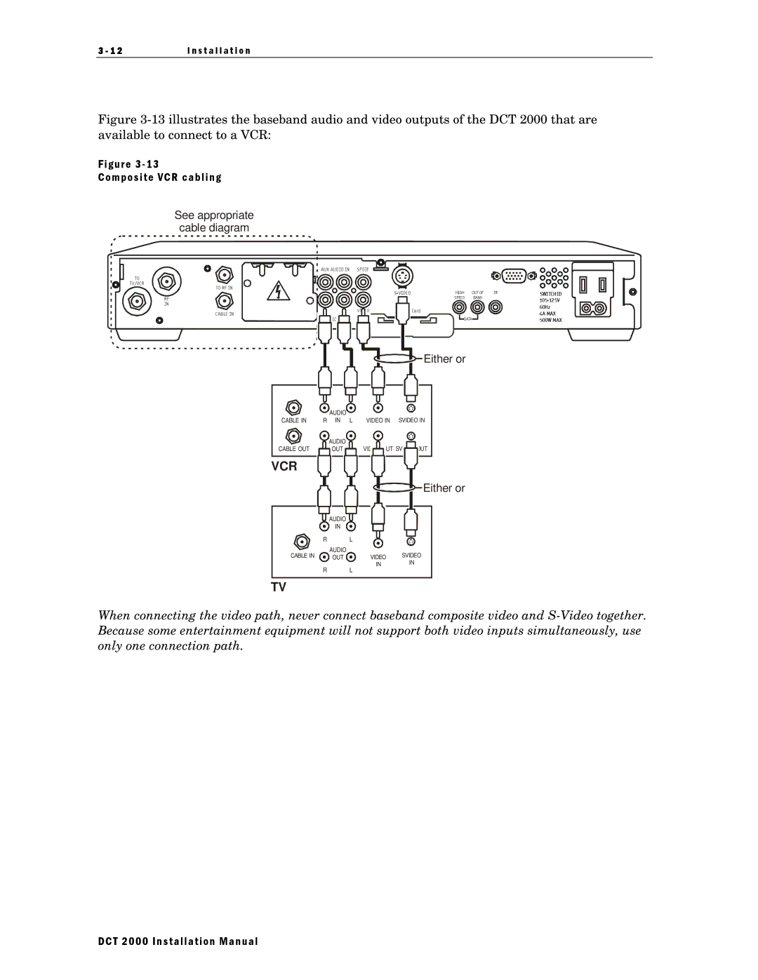
Figure 3-13 illustrates the baseband audio and video outputs of the DCT 2000 that are available to connect to a VCR:
Figure 3 - 13
Composite VCR cabling
See appropriate
cable diagram
AUX AUD IO IN SPDIF
TO |
T V/VCR |
TO RF IN |
|
|
| HIGH | OUT OF | IR | SWITCHED | |
RF |
|
|
| SPEED | BAND |
| |
|
|
|
|
|
| ||
IN |
|
|
|
|
|
| 60Hz |
|
| V IDEO |
| Card |
|
| |
CAB LE IN | R |
|
|
| 4A MAX | ||
|
|
|
|
| |||
|
| IO |
| DATA |
| 500W MAX | |
|
|
|
|
|
| ||
![]()
![]()
![]() Either or
Either or
|
|
|
|
|
|
|
|
|
|
|
|
|
|
|
|
|
|
|
|
|
|
|
|
|
|
|
|
|
|
|
|
|
|
|
|
|
|
|
|
|
|
|
|
|
|
|
|
|
|
|
|
|
|
|
|
| AUDIO |
|
|
|
|
|
|
|
|
|
|
| |||
CABLE IN | R IN L |
| VIDEO IN | SVIDEO IN | |||||||||||||
|
|
| AUDIO |
|
|
|
|
|
|
|
|
|
|
|
| ||
CABLE OUT |
|
|
| OUT |
|
|
|
|
|
|
| OUT |
|
|
| OUT | |
|
|
|
|
|
|
|
|
|
|
|
|
|
|
|
|
|
|
VCR
![]()
![]() Either or
Either or
![]()
![]() AUDIO
AUDIO ![]()
![]()
IN
|
|
|
|
|
|
|
|
| R | L |
|
|
| ||
CABLE IN | AUDIO |
|
|
| SVIDEO | ||
OUT | VIDEO | ||||||
|
| IN |
| IN | |||
| R | L |
|
|
| ||
TV
When connecting the video path, never connect baseband composite video and
DCT 2000 Installation Manual