1 - 2 | I n t r o d u c t i o n |
|
|
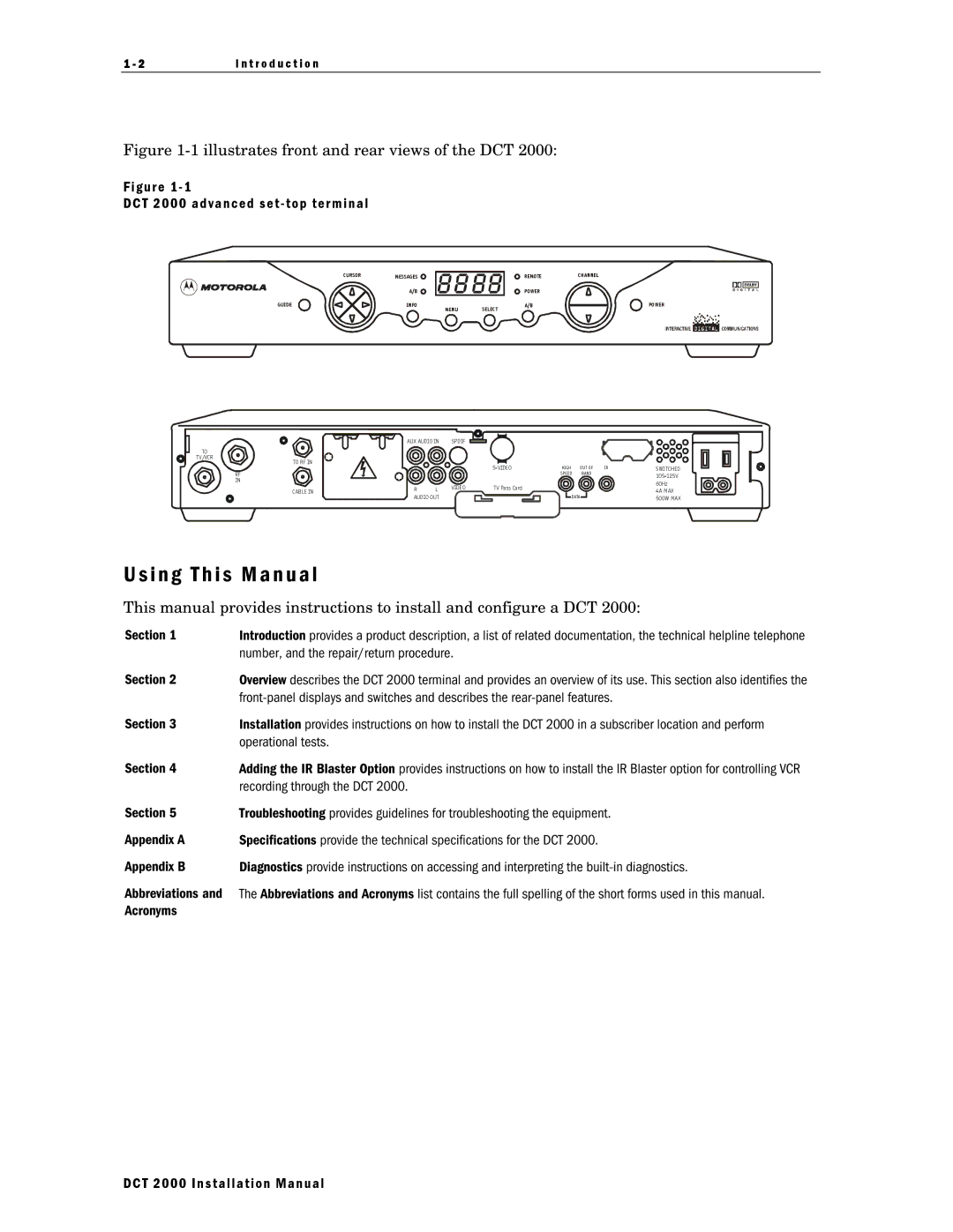
Figure 1-1 illustrates front and rear views of the DCT 2000:
Figure 1 - 1
DCT 2000 advanced set - top terminal
CURSOR | MESSAGES | REMOTE | CHANNEL |
| A/B | POWER |
|
GUIDE | INFO | A/B | POWER |
| MENU | SELEC T |
|
TO
TV/VCR
TO RF IN
RF
IN
CABLE IN
|
|
|
|
|
|
|
AUX AUDIO IN | SPDIF |
|
| |||
|
| |||||
|
|
|
|
|
|
|
|
|
|
|
|
|
|
|
|
|
|
| ||
R | L | VIDEO | TV Pass Card | |||
AUDIO OUT |
|
|
|
|
| |
|
|
|
|
|
|
|
|
|
|
|
|
|
|
HIGH | OUT OF | IR | SWI TCHED |
SPEED | BAND |
| |
|
|
|
60Hz 4A MAX
DATA | 500W MAX |
|
U s i n g T h i s M a n u a l
This manual provides instructions to install and configure a DCT 2000:
Section 1 | Introduction provides a product description, a list of related documentation, the technical helpline telephone |
| number, and the repair/return procedure. |
Section 2 | Overview describes the DCT 2000 terminal and provides an overview of its use. This section also identifies the |
| |
Section 3 | Installation provides instructions on how to install the DCT 2000 in a subscriber location and perform |
| operational tests. |
Section 4 | Adding the IR Blaster Option provides instructions on how to install the IR Blaster option for controlling VCR |
| recording through the DCT 2000. |
Section 5 | Troubleshooting provides guidelines for troubleshooting the equipment. |
Appendix A | Specifications provide the technical specifications for the DCT 2000. |
Appendix B | Diagnostics provide instructions on accessing and interpreting the |
Abbreviations and The Abbreviations and Acronyms list contains the full spelling of the short forms used in this manual. Acronyms
DCT 2000 Installation Manual