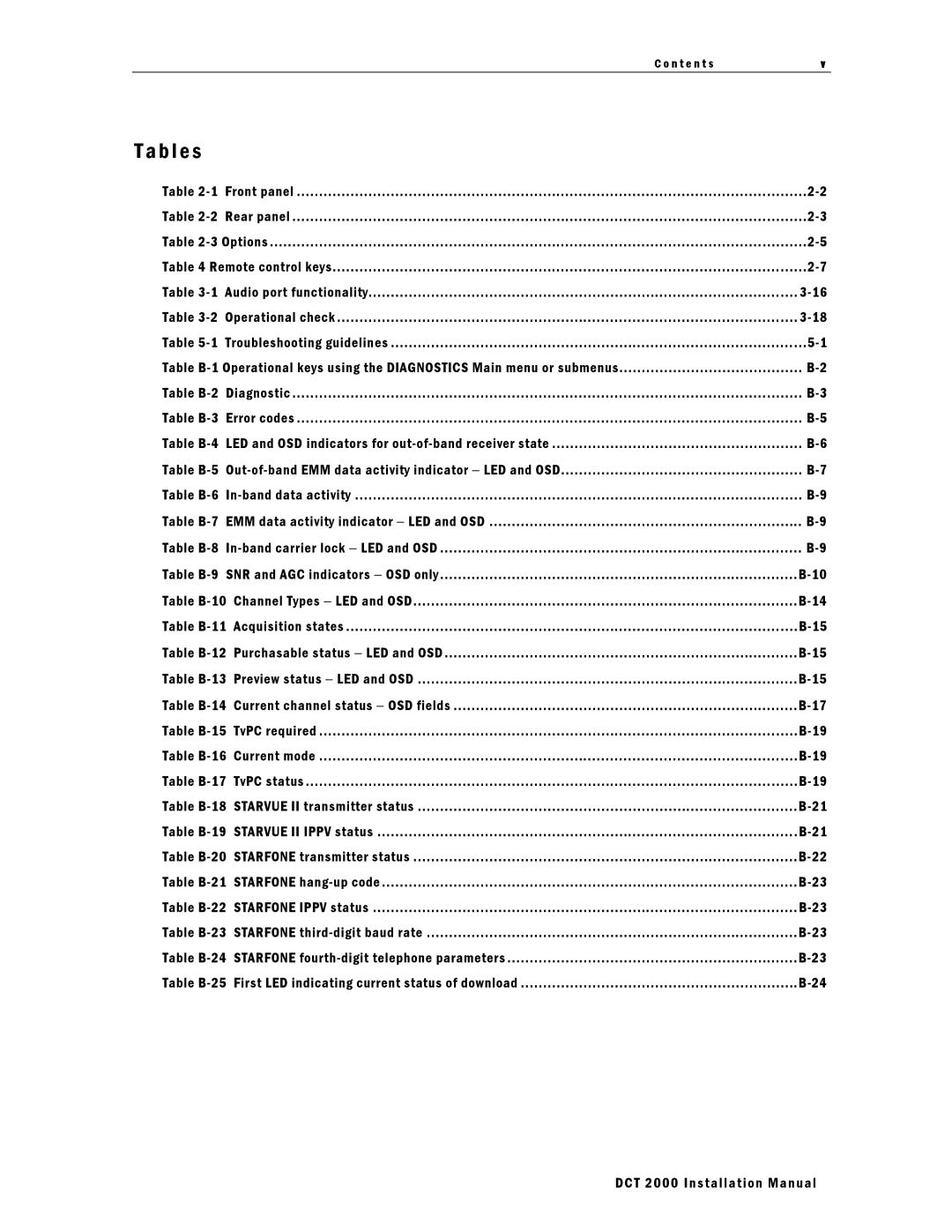
C o n t e n t s | v |
|
|
T a b l e s
Table | Front panel | t | t | 2 | |
Table | Rear panel | t | t | 2 | |
Table | t | t | 2 | ||
Table 4 Remote control keys | t | 2 | |||
Table | Audio port functionality | t | |||
Table | Operational check | t | |||
Table | Troubleshooting guidelines | t | 5 | ||
Table | ......................................... | ||||
Table | Diagnostic | t | t | ||
Table | Error codes | t | t | ||
Table | LED and OSD indicators for | t | |||
Table | t... | ||||
Table | t | ||||
Table | EMM data activity indicator − LED and OSD | t | |||
Table | t | ||||
Table | SNR and AGC indicators − OSD only | t | |||
Table | t | |||
Table | Acquisition states | t | ||
Table | Purchasable status − LED and OSD | t | ||
Table | Preview status − LED and OSD | t | ||
Table | Current channel status − OSD fields | t | ||
Table | TvPC required | t | ....t | |
Table | Current mode | t | ....t | |
Table | TvPC status | t | t | |
Table | STARVUE II transmitter status | t | ||
Table | STARVUE II IPPV status | t | ||
Table | STARFONE transmitter status | t | B22- | |
Table | t | |||
Table | STARFONE IPPV status | t | ||
Table | STARFONE | t | B23- | |
Table | STARFONE | t | ||
Table | First LED indicating current status of download | t | ||
DCT 2000 Installation Manual
