Section 4
A d d i n g t h e I R B l a s t e r O p t i o n
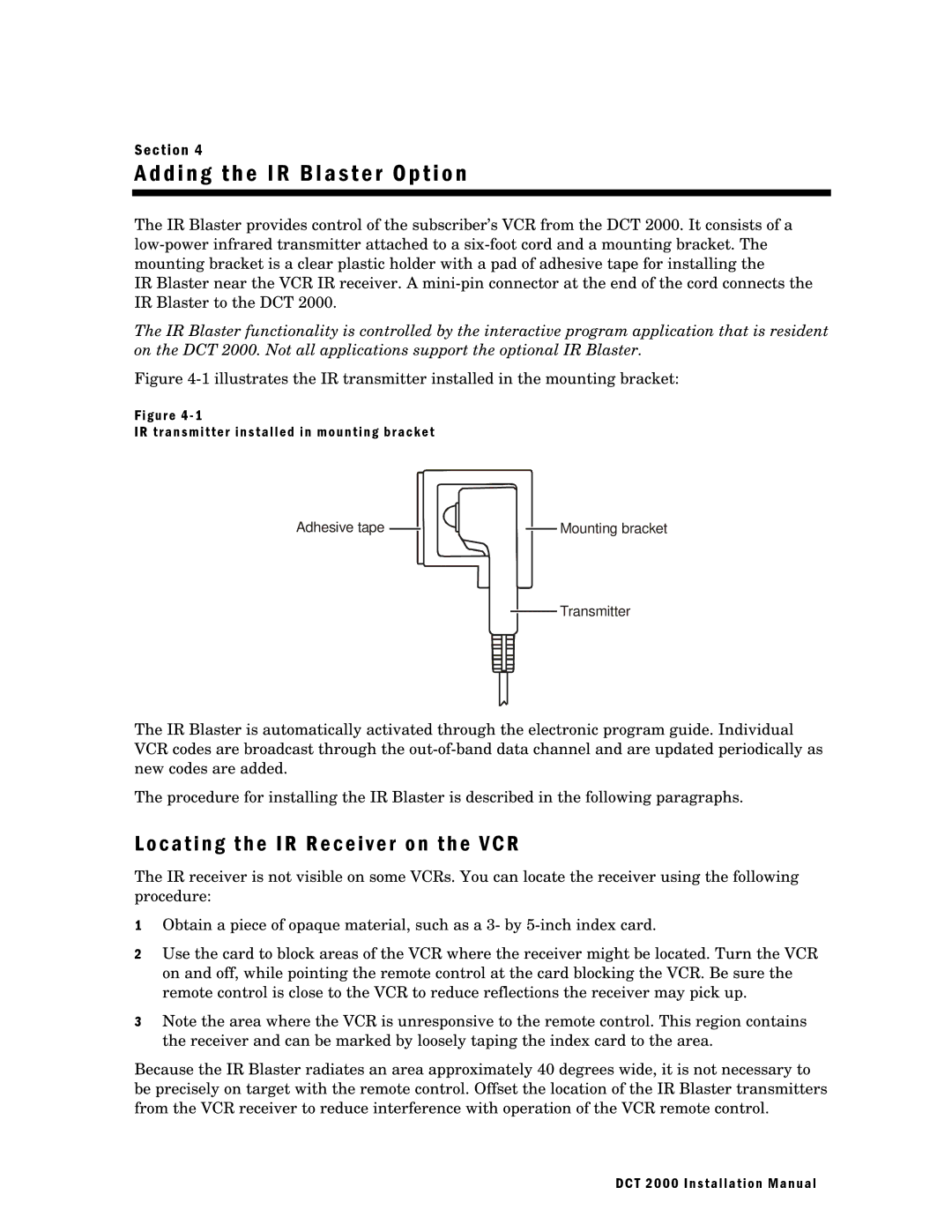
The IR Blaster provides control of the subscriber’s VCR from the DCT 2000. It consists of a
IR Blaster near the VCR IR receiver. A
The IR Blaster functionality is controlled by the interactive program application that is resident on the DCT 2000. Not all applications support the optional IR Blaster.
Figure 4-1 illustrates the IR transmitter installed in the mounting bracket:
Figure 4 - 1
IR transmitter installed in mounting bracket
Adhesive tape ![]()
![]() Mounting bracket
Mounting bracket
![]() Transmitter
Transmitter
The IR Blaster is automatically activated through the electronic program guide. Individual VCR codes are broadcast through the
The procedure for installing the IR Blaster is described in the following paragraphs.
L o c a t i n g t h e I R R e c e i v e r o n t h e V C R
The IR receiver is not visible on some VCRs. You can locate the receiver using the following procedure:
1Obtain a piece of opaque material, such as a 3- by
2Use the card to block areas of the VCR where the receiver might be located. Turn the VCR on and off, while pointing the remote control at the card blocking the VCR. Be sure the remote control is close to the VCR to reduce reflections the receiver may pick up.
3Note the area where the VCR is unresponsive to the remote control. This region contains the receiver and can be marked by loosely taping the index card to the area.
Because the IR Blaster radiates an area approximately 40 degrees wide, it is not necessary to be precisely on target with the remote control. Offset the location of the IR Blaster transmitters from the VCR receiver to reduce interference with operation of the VCR remote control.
DCT 2000 Installation Manual
