D i a g n o s t i c s | B - 3 |
|
|
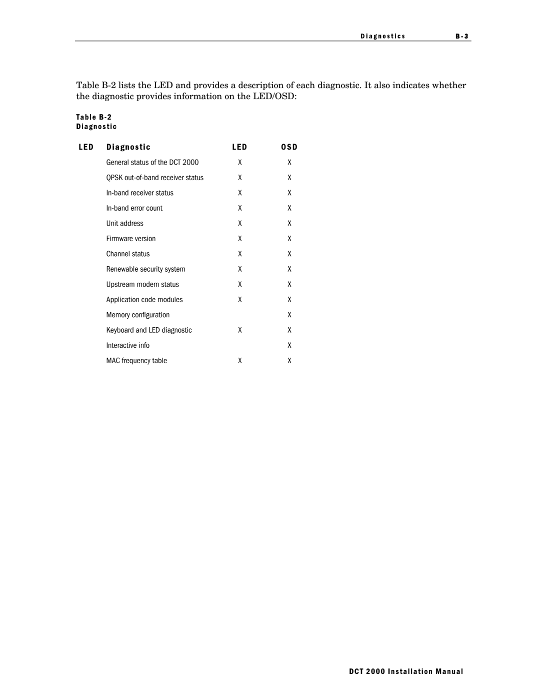
Table
Table B - 2
Diagnostic
LED | Diagnostic | LED | OSD |
d 01 | General status of the DCT 2000 | X | X |
d 02 | QPSK | X | X |
d 03 | X | X | |
d 04 | X | X | |
d 05 | Unit address | X | X |
d 06 | Firmware version | X | X |
d 07 | Channel status | X | X |
d 08 | Renewable security system | X | X |
d 09 | Upstream modem status | X | X |
d 10 | Application code modules | X | X |
d 11 | Memory configuration |
| X |
d 12 | Keyboard and LED diagnostic | X | X |
Interactive info |
| X | |
d 14 | MAC frequency table | X | X |
DCT 2000 Installation Manual
