3 - 4 | I n s t a l l a t i o n |
|
|
S t a n d a r d V C R C a b l i n g D i a g r a m
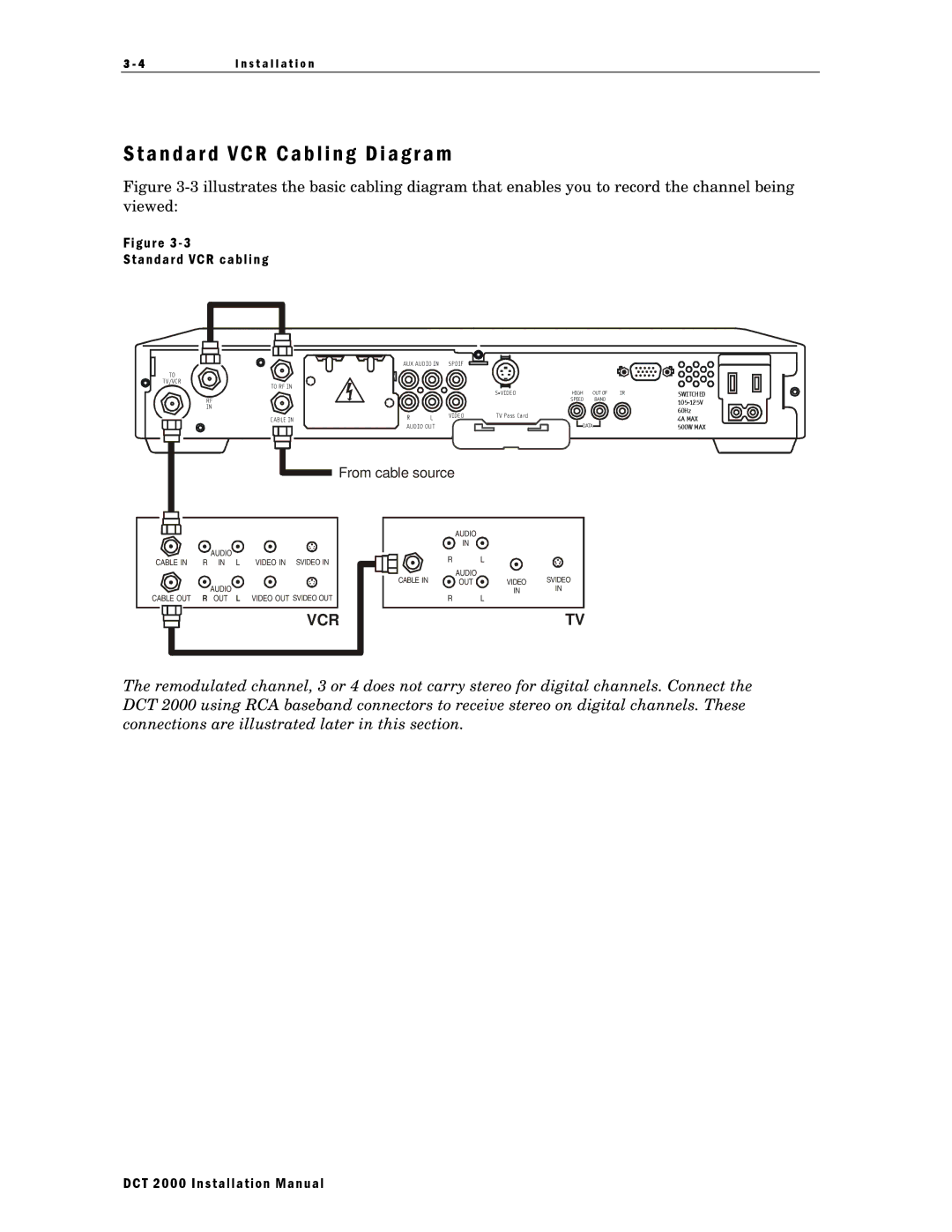
Figure 3-3 illustrates the basic cabling diagram that enables you to record the channel being viewed:
F i g u r e 3 - 3
S t a n d a r d V C R c a b l i n g
TO
TV/VCR
TO RF IN
RF
IN
CAB LE IN
AUX AUDIO IN | SPDIF |
|
|
|
|
| |
|
|
| HIGH | OUT OF | IR | SWITCHED | |
|
|
|
| SPEED | BAND |
| |
|
|
|
|
|
|
| |
|
|
|
|
|
|
| 60Hz |
R | L | VIDEO | T V Pass Card |
|
|
| 4A MAX |
|
|
|
|
| |||
AUDIO OUT |
|
| DATA |
| 500W MAX | ||
|
|
|
|
| |||
![]() From cable source
From cable source
|
|
|
|
|
|
|
|
|
|
|
|
|
| AUDIO |
|
|
|
|
|
|
|
|
|
|
|
|
|
|
|
|
|
| |
|
|
|
|
|
|
|
|
|
|
|
|
|
|
|
| |
|
|
|
|
|
|
|
|
|
|
|
|
|
|
|
| |
|
|
|
|
|
|
|
|
|
|
|
|
|
| IN |
|
|
|
|
|
|
|
| AUDIO |
|
|
|
|
|
| R |
| L |
|
|
|
|
|
|
|
|
|
|
|
|
|
|
| |||
CABLE IN | R | IN | L | VIDEO IN SVIDEO IN |
|
|
|
|
|
| ||||||
|
|
|
|
|
|
|
|
|
|
|
|
|
| AUDIO |
| SVIDEO |
|
|
|
|
|
|
|
|
|
|
|
|
|
|
| ||
|
|
|
|
|
|
|
|
|
|
|
| CABLE IN |
| |||
|
|
|
|
|
|
|
|
|
|
|
| OUT | VIDEO | |||
|
|
|
|
| R | AUDIO | L |
|
|
|
|
|
|
| IN | IN |
CABLE OUT | OUT | VIDEO OUT SVIDEO OUT |
|
|
|
| R |
| L |
| ||||||
|
|
|
|
|
|
|
| VCR |
|
|
|
|
|
|
| TV |
|
|
|
|
|
|
|
|
|
|
|
|
|
|
| ||
|
|
|
|
|
|
|
|
|
|
|
|
|
|
| ||
The remodulated channel, 3 or 4 does not carry stereo for digital channels. Connect the DCT 2000 using RCA baseband connectors to receive stereo on digital channels. These connections are illustrated later in this section.
DCT 2000 Installation Manual