3 - 2 | I n s t a l l a t i o n |
|
|
S t a n d a r d C a b l i n g D i a g r a m
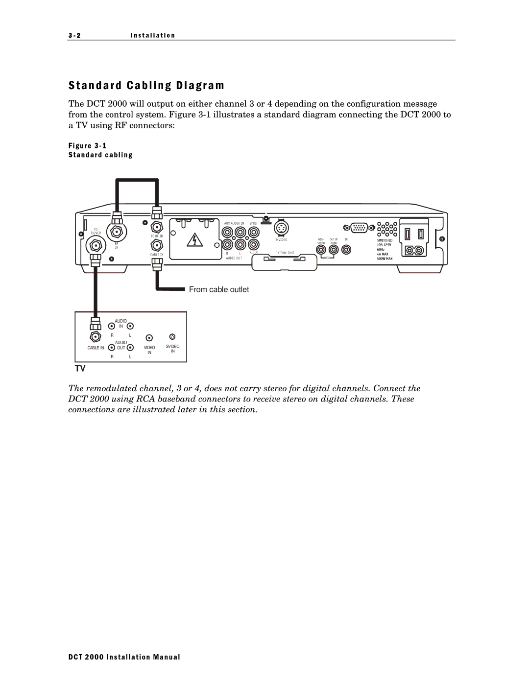
The DCT 2000 will output on either channel 3 or 4 depending on the configuration message from the control system. Figure
Figure 3 - 1
Standard cabling
TO
TV/VCR
TO RF IN
RF
IN
CAB LE IN
AUX AUDIO IN | SPDIF | |
R | L | VIDEO |
| ||
AUDIO OU T
HIGH | OUT OF | IR | SWITCHED | |
|
|
| ||
| SPEED | BAND |
| |
|
|
|
|
|
|
|
|
|
|
| 60Hz |
T V Pass Card | 4A MAX | ||||||
|
|
|
|
|
|
| |
|
|
|
|
| DATA |
| 500W MAX |
|
|
|
|
|
|
|
|
|
|
|
|
|
|
|
|
![]() From cable outlet
From cable outlet
AUDIO
IN
| R | L |
|
| AUDIO |
| SVIDEO |
CABLE IN | OUT | VIDEO | |
|
| IN | IN |
| R | L |
|
TV
The remodulated channel, 3 or 4, does not carry stereo for digital channels. Connect the DCT 2000 using RCA baseband connectors to receive stereo on digital channels. These connections are illustrated later in this section.
DCT 2000 Installation Manual