I n s t a l l a t i o n | 3 - 1 5 |
|
|
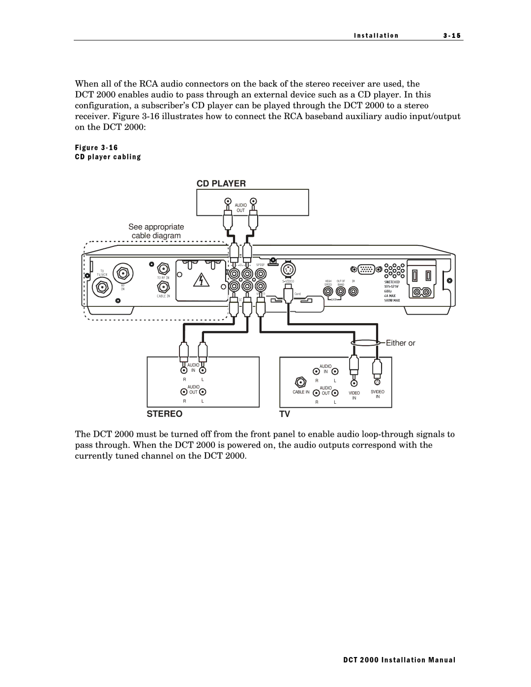
When all of the RCA audio connectors on the back of the stereo receiver are used, the DCT 2000 enables audio to pass through an external device such as a CD player. In this configuration, a subscriber’s CD player can be played through the DCT 2000 to a stereo receiver. Figure
Figure 3 - 16
CD player cabling
CD PLAYER
AUDIO
OUT
See appropriate
cable diagram
|
|
|
|
|
|
|
|
|
|
|
|
|
|
|
|
|
|
|
|
|
|
|
| AUD |
|
| SPDIF | ||
TO |
T V/VCR |
TO RF IN |
| HIGH | OUT OF | IR | SWITCHED | |
RF |
| SPEED | BAND |
| |
|
|
|
| ||
IN |
|
|
|
| 60Hz |
V IDEO |
| Card |
|
| |
|
|
| 4A MAX | ||
CAB LE IN |
|
|
|
| |
IO |
| DATA |
| 500W MAX | |
|
|
|
| ||
![]()
![]() Either or
Either or
|
|
|
|
|
|
|
|
|
|
|
|
|
|
|
|
|
|
|
|
|
|
|
|
|
|
|
|
|
|
|
|
|
|
|
|
|
|
|
|
|
|
|
| AUDIO |
|
|
|
| AUDIO |
|
|
|
|
|
|
|
|
| |
|
|
|
|
|
|
|
|
|
|
|
|
|
|
|
| ||||
|
|
|
| IN |
|
| IN |
|
|
|
|
|
|
|
|
| |||
|
| R |
|
| L |
|
|
|
|
|
|
|
|
|
|
|
| ||
|
|
|
|
| R |
| L |
|
|
|
|
|
|
| |||||
|
|
|
| AUDIO |
|
| AUDIO |
| VIDEO SVIDEO | ||||||||||
|
|
|
| OUT |
| CABLE IN | OUT |
| |||||||||||
|
| R |
|
| L |
|
|
|
| IN |
| IN | |||||||
|
|
|
|
| R |
| L |
|
|
| |||||||||
STEREO |
|
|
|
|
| TV |
|
|
|
|
|
|
|
|
|
| |||
The DCT 2000 must be turned off from the front panel to enable audio
DCT 2000 Installation Manual