O v e r v i e w | 2 - 3 |
|
|
R e a r P a n e l
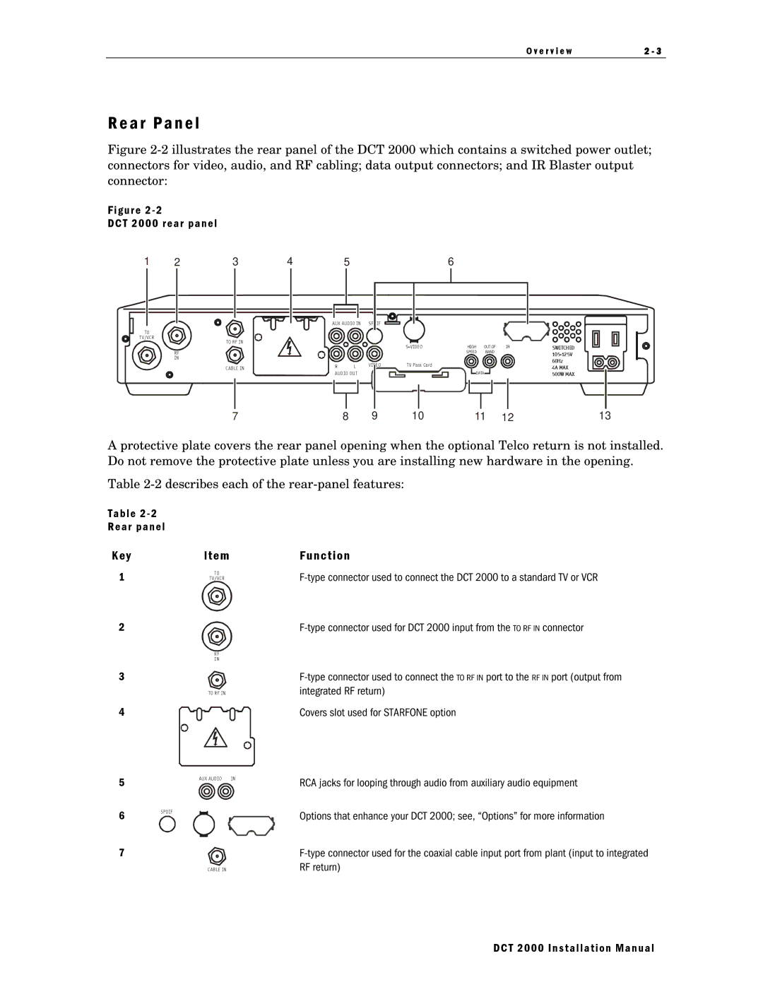
Figure 2-2 illustrates the rear panel of the DCT 2000 which contains a switched power outlet; connectors for video, audio, and RF cabling; data output connectors; and IR Blaster output connector:
F i g u r e 2 - 2
D C T 2 0 0 0 r e a r p a n e l
1 | 2 | 3 |
TO |
|
|
TV/VCR |
| TO RF IN |
|
| |
| RF |
|
| IN |
|
|
| CAB LE IN |
7
4 | 5 | 6 |
AUX AUD IO IN SPDIF
|
|
| HIGH | OUT OF | IR | SWITCHED | |
|
|
|
| SPEED | BAND |
| |
|
|
|
|
|
|
| |
|
|
|
|
|
|
| 60Hz |
R | L | V IDEO | T V Pass Card |
|
|
| 4A MAX |
AUD IO OU T |
|
| DATA |
| 500W MAX | ||
8 | 9 | 10 | 11 | 12 | 13 |
A protective plate covers the rear panel opening when the optional Telco return is not installed. Do not remove the protective plate unless you are installing new hardware in the opening.
Table
T a b l e 2 - 2
R e a r p a n e l
K e y
1
2
3
4
5
6
7
I t e m
TO
TV/VCR
R F
I N
TO R F IN
AUX AUDIO | IN |
SPDIF
CAB LE IN
F u n c t i o n
Covers slot used for STARFONE option
RCA jacks for looping through audio from auxiliary audio equipment
Options that enhance your DCT 2000; see, “Options” for more information