I n s t a l l a t i o n | 3 - 3 |
|
|
S T A R F O N E m o d u l e c a b l i n g d i a g r a m
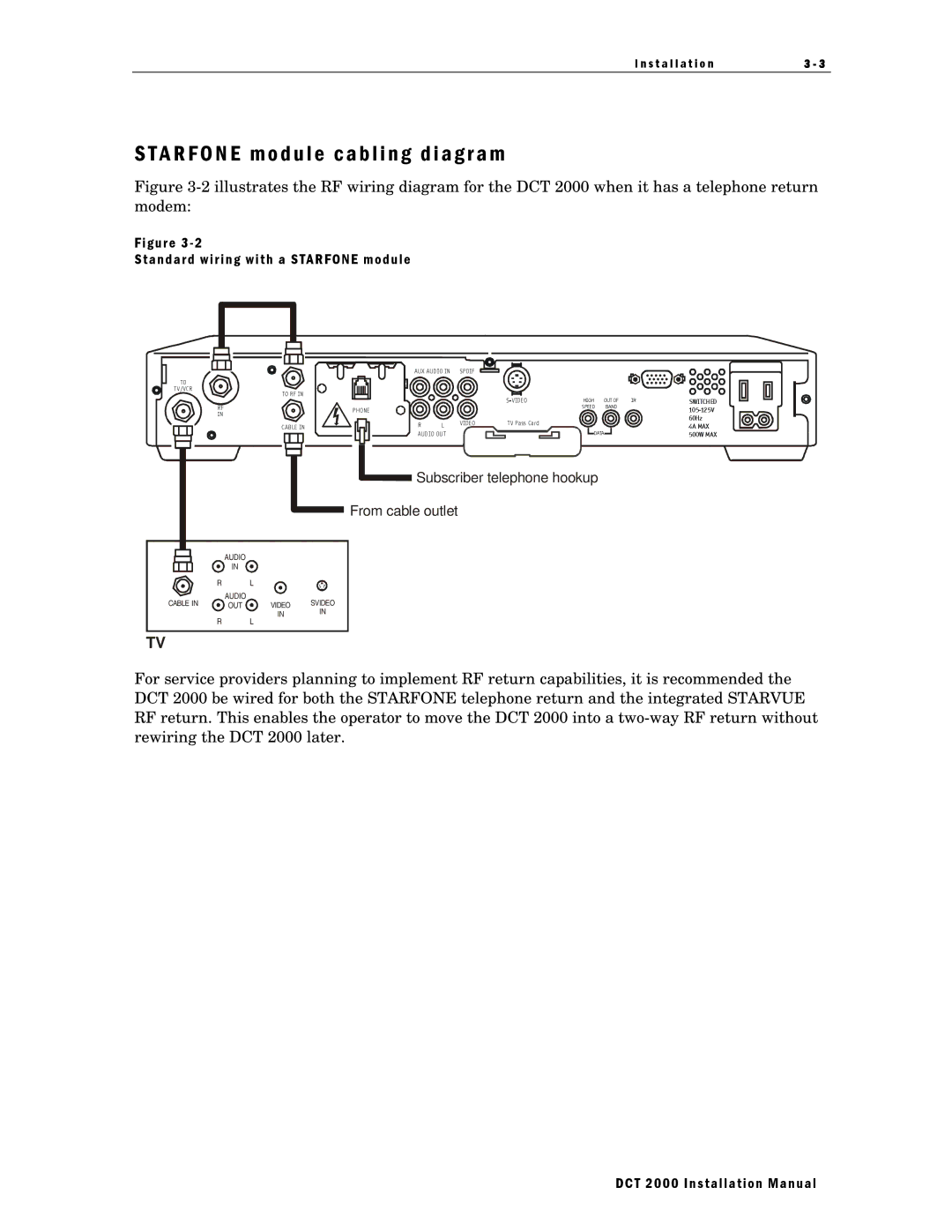
Figure 3-2 illustrates the RF wiring diagram for the DCT 2000 when it has a telephone return modem:
Figure 3 - 2
Standard wiring with a STARFONE module
TO
TV/VCR
TO RF IN
RF
IN
CAB LE IN
PHONE
AUX AUDIO IN | SPDIF |
|
|
|
|
| |
|
|
| HIGH | OUT OF | IR | SWITCHED | |
|
|
|
| SPEED | BAND |
| |
|
|
|
|
|
|
| |
|
|
|
|
|
|
| 60Hz |
R | L | VIDEO | T V Pass Card |
|
|
| 4A MAX |
|
|
|
|
| |||
AUDIO OUT |
|
| DATA |
| 500W MAX | ||
|
|
|
|
| |||
![]() Subscriber telephone hookup
Subscriber telephone hookup
From cable outlet
AUDIO
IN
R |
| L |
|
CABLE IN | AUDIO |
| SVIDEO |
OUT | VIDEO | ||
|
| IN | IN |
R L
TV
For service providers planning to implement RF return capabilities, it is recommended the DCT 2000 be wired for both the STARFONE telephone return and the integrated STARVUE RF return. This enables the operator to move the DCT 2000 into a
DCT 2000 Installation Manual